


ADCP-50-304 • Issue 19 • June 1999 • Section 4: PatchSwitch X.21
Page 4-7
© 1999, ADC Telecommunications, Inc.
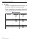
3.4 Status Indication Modules
The six X.21 circuit leads having LED indicators are: T, C, R, I, S, and B. When a monitored
circuit lead is active (signal present), the associated LED indicator turns on only while the
signal is present. The colors and signal definitions for the applicable Led Status indicators
shown in Table 4-1.
3.5 Alarm Modules
Two time-out alarm functions are provided.
Alarm A Monitors the time between the raising of C lead and the raising of the I lead during
the call request phase. If this value is greater than the user selected interval, the A
alarm LED and/or audible alarm is activated.
Alarm B Monitors the time between the dropping of the I lead and the dropping of the C lead
or the dropping of the C lead and the dropping of the I lead, during the call clear
phase. If this value is greater than the user selected interval, the B alarm LED and/or
audible alarm is activated.
The alarm is indicated by the amber LED and/or an audible alarm located in the chassis. Both
alarms have independent variable delays and can be turned off.
The three position toggle switch located on the front panel allows the following choices:
ALM Visual and Audible alarms on.
OFF Visual and Audible alarms off.
LED Visual alarm only.
3.6 Alarm Reset
To reset the alarm on the PSM-832002 push the switch marked RST. To reset alarm on all other
alarm modules touch the the pads marked RST. If alarm condition has not cleared, the alarm
will time-out, and alarm will be tripped again.
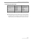
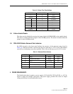
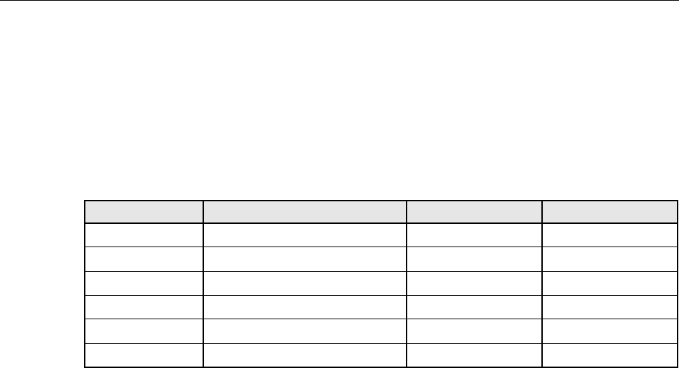
Table 4-1. Signal Status
ABBREVIATION SIGNAL NAME/LEAD LED COLOR SIGNAL ORIGIN
T Transmit Green DTE
C Control Green DTE
R Receive Red DCE
I Indication Red DCE
S Signal Element Timing Red DCE
B Byte Timing Red DCE