


ADCP-50-304 • Issue 19 • June 1999 • Section 3: PatchSwitch V.35
Page 3-1
© 1999, ADC Telecommunications, Inc.
SECTION 3: PATCHSWITCH V.35
1 PRODUCT OFFERING . . . . . . . . . . . . . . . . . . . . . . . . . . . . . . . . . . . . . . . . . . . . . . . . . . . . . . . . . . . . . . . . . . . .3-1
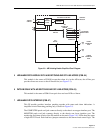
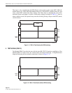
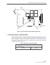
2 APPLICATION WITH EXISTING UNITS . . . . . . . . . . . . . . . . . . . . . . . . . . . . . . . . . . . . . . . . . . . . . . . . . . . . . . . . .3-2
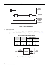
3 FUNCTION SELECTION-MODULES . . . . . . . . . . . . . . . . . . . . . . . . . . . . . . . . . . . . . . . . . . . . . . . . . . . . . . . . . . .3-4
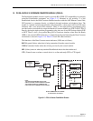
4 FUNCTIONAL SELECTION—CONVERSION BOARD . . . . . . . . . . . . . . . . . . . . . . . . . . . . . . . . . . . . . . . . . . . . . . . .3-5
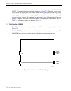
5 HARDWARE INSTALLATION. . . . . . . . . . . . . . . . . . . . . . . . . . . . . . . . . . . . . . . . . . . . . . . . . . . . . . . . . . . . . . . .3-8
6 RECOMMENDED MATING CONNECTOR PARTS. . . . . . . . . . . . . . . . . . . . . . . . . . . . . . . . . . . . . . . . . . . . . . . . . . .3-9
_________________________________________________________________________________________________________
1 PRODUCT OFFERING
The ADC V.35 PatchSwitch makes available four modules, four conversion boards and the necessary
conversion patchcords for use with the 34-pin “V.35 Interface” data communications hardware.
The units are designed to be compatible with the RDC-01, RDC-02, PSC-01, and PSC-02
standard PatchSwitch chassis. The V.35 modules utilize grey front panels so they can be mixed
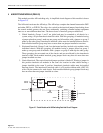
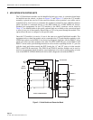
with other interfaces and still be identified a V.35 circuits. The modules provide monitor and
patch access in the Serial Binary Data Interchange (SBDI) portion of data communications
circuit. Some modules also provide local and remote alarming as well as signal status
indication. A more detailed description of each module is given in Table 3-1. The SBDI is
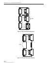
typically found between the MODEM (DCE) and the TERMINAL/COMPUTER (DTE). A
single circuit requires one module and one conversion board which connects between DTE-A or
DTE-B and DCE. Switching takes place between DTE-A and DTE-B to connect to DCE. As an
alternative to the V.35 conversion boards, V.35 cables using DB-25 connectors can be used to
attach easily to the RDC-01/PSC-01 and RDC-02/PSC-02 PatchSwitch chassis.
Content Page
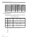
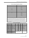
Table 3-1. Product Description
PSM-16 PatchSwitch Module provides monitor, patch access and A/B Switching for DTE-A or
DTE-B and DCE plus V.35 LED signal indication and circuit loss alarming.
PSM-17 PatchSwitch Module provides monitor, patch access and A/B Switching for DTE-A or
DTE-B and DCE.
PSM-18 Interface Module provides patch access for test and/or line monitor equipment, plus LED
signal indication and circuit loss alarming.
PSM-19 Interface Module provides patch access for test, and/or line monitor equipment.
FFM-01 PatchSwitch Conversion Board with female/female/male V.35 connectors and three male
DB-25 connectors. Intended for use with the RDC-01/PSC-01 PatchSwitch chassis.
FFM-02 PatchSwitch Conversion Board with female/female/male V.35 connectors and male/
male/female DB-25 connectors. Intended use on the RDC-02/PSC-02 PatchSwitch chassis.
FF-01 PatchSwitch Conversion board with female/female V.35 connectors and male/male DB-25
connectors. Intended for use with RDC-01/PSC-01 and RDC-02/PSC-02 PatchSwitch
chassis to accommodate PSM-18 or PSM-19 Patch Interface Modules.
FF-02 PatchSwitch Conversion board with female/male V.35 connectors and male/female DB-25
connectors. Intended for use with RDC-02/PSC-02 PatchSwitch chassis to accommodate
PSM-18 or PSM-19 Patch Interface Modules.