


ADCP-50-304 • Issue 19 • June 1999 • Section 4: PatchSwitch X.21
Page 4-9
© 1999, ADC Telecommunications, Inc.
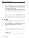
3.8 B Alarm Enable/Disable
The alarm can be disabled by moving the jumper labeled ALMB/ALMB on the module board.
The alarm is enabled when the jumper is in the ALMB position. The alarm is disabled when the
jumper is in the ALMB position.
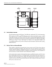
3.9 PSM-832002 Module Quiescent State Indicators
Six LEDs located on the front panel indicate the presence of the quiescent states found in
Table 4-4. When the module is powered up and not connected to a X.21 circuit LED number
one will be on indicating a state one condition. This is like an idle state on a live X.21 circuit.
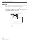
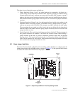
4 POWER REQUIREMENTS
The PatchSwitch chassis requires a power supply (110 Vac/60 Hz, 220 Vac/50 Hz, or –48 Vdc
input) to supply the modules with power. The power supply provides the correct dc output
voltage and current for the PatchSwitch chassis.
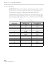
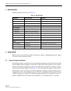
Table 4-3. B Alarm Time Delay Settings
ARC LENGTH SWITCH POSITION TIME DELAY
V0None
Shortest 1 55 msec
2 117 msec
3 242 msec
4 492 msec
5 992 msec
6 1.9 sec
Longest 7 3.9 sec
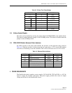
Table 4-4. Quiescent State Indicators
STATE DTE DCE LED COLOR
1 Ready Ready Green
14 Controlled Not Ready Ready Red
18 Ready Not Ready Red
22 Uncontrolled Not Ready Not Ready Red
23 Controlled Not Ready Not Ready Red
24 Uncontrolled Not Ready Ready Red