


ADCP-50-304 • Issue 19 • June 1999 • Section 3: PatchSwitch V.35
Page 3-4
© 1999, ADC Telecommunications, Inc.
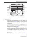
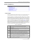
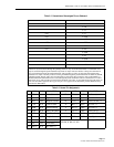
3 FUNCTION SELECTION-MODULES
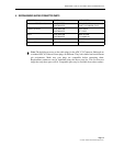
Several optional items shown in Table 3-3 should be considered before any PSM-16 or PSM-18
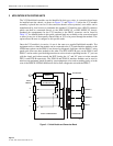
modules are placed into service. Factory settings are noted, refer to Figure 3-3 table for item
locations. If factory settings are acceptable, no action is required.
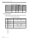
* This screwdriver adjustment is made at the rotary switch on the face of the module near the bottom. Note the length of the lines
around the switch, the longer the line, the greater the time delay. Switch position 8 is straight up.
Sw Pos TD
8 None
7 62.5 msec
6 250 msec
5 500 msec
4 1.0 sec
3 8.0 sec
2 32.0 sec
1 64.0 sec
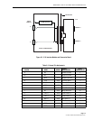
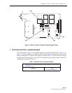
V RC (+) DCE Rec Clck (+) 17
X RC (–) DCE Rec Clck (–) 18
Y TC (+) DCE Trans Clck (+) 15
AA TC (–) DCE Trans Clck (–) 16
MM BSY DCE Busy Signal 25
K, L, M, N, Z, BB, CC,
DD, EE, FF, HH, JJ, KK,
LL, NN
Unassigned Pins
Table 3-3. Optional Items on the Module
ITEM DESCRIPTION FUNCTION
A
Trans Clk Source
(Factory Setting)
DTE DCE
W,U AA, Y
X
B Alarm Sig Source
(Factory Setting)
TD RD RTS CTS RC DTR DCD TC
C Alarm Reset Polarity
(Factory Setting)
ALM+ ALM
X
DAlarm Reset
(Factory Setting)
AUTO MANUAL
NOT-LCHD (LCHD)
X
E Alarm Delay
(Factory Setting)
NO YES
*SW pos 8 7 6 5 4 3 2 1
X
Table 3-2. Normal Pin Assignments, continued
V.35 PIN NAME ORIGIN
SIGNAL
DESCRIPTION
DB-25
CONNECTOR PIN