


ADCP-50-304 • Issue 19 • June 1999 • Section 7: Operation
Page 7-11
© 1999, ADC Telecommunications, Inc.
6.18.2 Module Position Entries
Some displays are instructions to enter the numerical module positions of A/B Switch Modules.
To enter module numbers enter each number, separated by commas (Example: 3, 7, 11, 14) and
press RETURN. The comma is always used as an input delimiter.
Two or more A/B Switch Module numbers in a sequence may be entered as a group by entering
the lowest and highest numbers in the sequence, separated by a dash (Example: l-4). Entering 3-
l5 will select modules 3 through 15. To enter all module numbers, only the letter A needs to be
entered.
6.18.3 Control Key
The Ctrl X key may be pressed at any time during TLKxx operation to return control to the
previous menu or deselect the chassis.
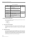
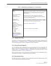
6.18.4 Status Displays
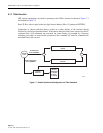
Various types of switch displays occur frequently in establishing switch configurations. These
are described in Table 7-2.
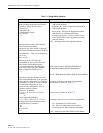
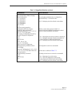
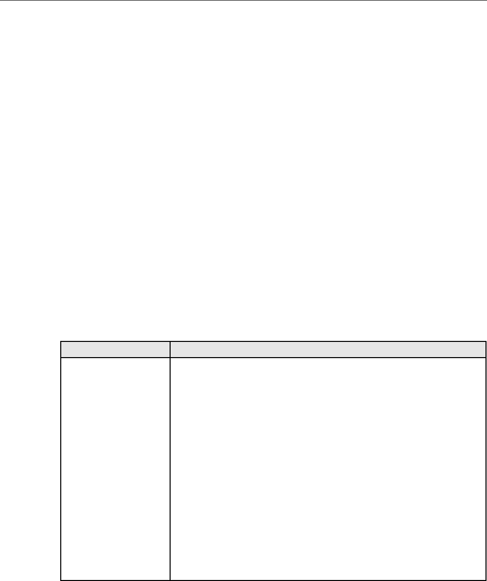
Table 7-2. Status Displays
STATUS DISPLAY DISPLAY DEFINITION
Status Display #1
Chassis No. Xx Chassis No. XX — XX = the chassis number for which status is displayed.
Module # 1 2 3 4 5 6 7 8
9 10 11 12 13 14 15
Module # — Module numbers on selected chassis for which switch status
is displayed. Module 0 is defined as the module in the leftmost position in
the chassis.
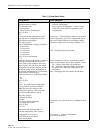
Sw Status a/b/n/m/l/q/-
Failed Act
Sw Status — Current switch status on each of the indicated modules.
a — Equipment channel A is selected on A/B Switch Modules.
b — Equipment channel B is selected on A/B Switch Modules.
n — Normal Mode is selected on Test Access Modules.
m — Monitor Mode is selected on Test Access Modules.
l — Line Mode is selected on Test Access Modules.
q — Equipment Mode is selected on Test Access Modules.
- — Indicates blank slot (not occupied by any module).
Failed Act — Previous command did not execute correctly.
^ — Indicated module failed to perform command action.
Blank - Indicated module completed command action.