


ADCP-50-304 • Issue 19 • June 1999 • Section 6: Installation
Page 6-3
© 1999, ADC Telecommunications, Inc.
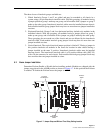
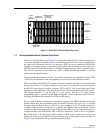
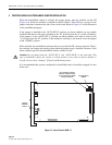
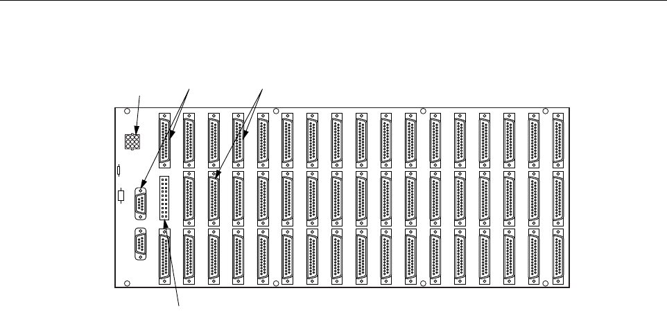
Figure 6-1. RDC-01/02 PatchSwitch Chassis Rear View
1.5 Communications Network Interface Connections
The back of each PS chassis (see Figure 6-1) contains 50 standard D-sub 25 pin connectors used
to interface PatchSwitch modules with a communications network. In the top row, beginning at
the right in the illustration, the first 16 connectors (DTE A) are for connecting PatchSwitch
modules to Computer circuits via customer supplied cables. The 16 connectors in the center row
(DTE B) connect PatchSwitch modules to alternate Computer circuits via user supplied cables.
The first 16 connectors in the bottom row (DCE), connect PatchSwitch modules to modem
circuits via user supplied cables.
The top and bottom connectors of slot 17 are usually connected to test equipment so that a DTE
or DCE may be connected to the test equipment via patch cord and the interface module.
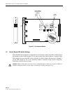
With the PSR-06 RS-422/RS-232 Interface Converter Module installed in the PatchSwitch
chassis (slot position 17), the top connector of slot position 17 provides the connection point for
the RS-232 control device (modem, computer, CRT or RCU). Two 9-pin female type D-sub
connectors on the backplane of the chassis provide for CM interface with another PS chassis.
The bottom connector of slot position 17 is not used in this case. An eight position
programming plug is provided on the PSR-06 Interface Converter printed circuit board for
assigning the PatchSwitch assembly as a DTE or DCE device.
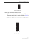
When system is directly connected to a terminal or computer the PSR-06 Interface Converter
module should have the programming plug in the DCE position (see Figure 6-2). A straight
through cable can then be used to connect the top connector of slot 17 to the terminal of
computer. When system is connected to a modem, the PSR-06 Interface Converter module
should have the programming plug in the DTE position. Make sure the programming plug is
inserted into the correct DIP Socket, DTE or DCE as appropriate. There is also a two position
Berg Strap used on the Berg Posts labeled DSR. In DTE mode, position the strap on the
bottom and center post and in DCE mode position the strap on the top and center post. Refer to
Figure 6-2 for illustration of Berg strap and programming plug.
POWER
SUPPLY
CONNECTOR
INTERFACE
CONNECTORS
COMMUNICATIONS
CHANNEL
CONNECTORS
INTERCHASSIS
INTERLOCK
DTE (A)
CONNECTORS
DTE (B)
CONNECTORS
DCE
CONNECTORS
1559-A