


ADCP-50-304 • Issue 19 • June 1999 • Section 2: Functional Description
Page 2-12
© 1999, ADC Telecommunications, Inc.
4 A/B SWITCHING MODULE (PSM-03)
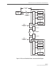
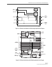
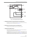
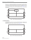
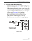
This module provides A/B switching only. A simplified circuit diagram of this module is shown
in Figure 2-8.
The A/B switch activates the A/B relays. The A/B relays complete the channel between the DCE
and either DTE-A or DTE-B. The relays also switch in the interlock jumper. Interlocking from
the control module protects the user from accidentally switching common backup equipment
onto two or more different data lines. The three classes of interlock groups available are:
1. Global Interlock: Groups 1 and 2 are global and may be extended to all chassis in a
system, using a 20-pin interchassis interlock cable. With this grouping, all modules having
a jumper placed on group 1 make up one group, and all modules with a jumper on group 2
make up the other group. Interchassis interlock cables must be installed between chassis.
Each module interlock group may have no more than one jumper installed at one time.
2. Horizontal Interlock: Groups 3 and 4 are horizontal and they include only modules in the
individual chassis. With this grouping, all modules having a jumper placed on group 3
make up one group and all modules with a jumper on group 4 make up the other group.
These groupings do not extend out of the chassis and are not affected by the interchassis
interlock cable. Each module interlock group jumper block may have no more than one
jumper installed at a time.
3. Vertical Interlock: The vertical interlock jumper position is labeled V. Placing a jumper in
this position interlocks all modules in the same slot location in other chassis having a
jumper installed on the came V position. Interchassis interlock cables must be installed
between chassis. The interchassis interlock cable is a 20 position ribbon cable (4WC-03)
with a 20-pin connector for each chassis. Each module interlock group jumper block may
have no more than one jumper installed at a time.
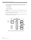
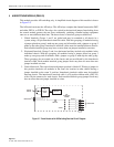
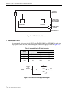
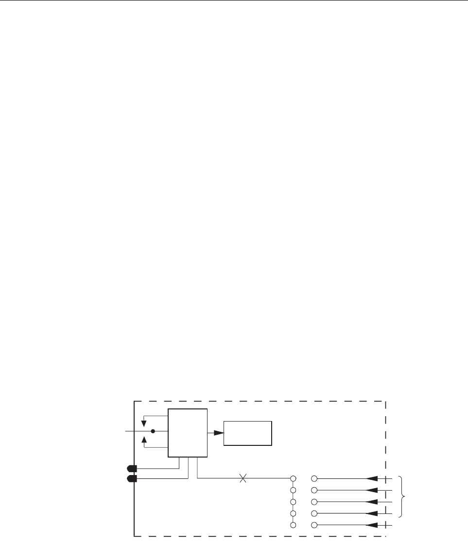
Figure 2-7. Patch Module with A/B Switching Detailed Circuit Diagram
A/B
SWITCH
LOGIC
A/B
REPLAYS
A/B
INTERLOCK
JUMPER
GROUP 1
2
3
4
V
ALARM
A/B
REPLAYS
INDICATORS
TOGGLE
SWITCH
A
B
A
B
BACKPLANE
1612-A