


ADCP-50-304 • Issue 19 • June 1999 • Section 6: Installation
Page 6-7
© 1999, ADC Telecommunications, Inc.
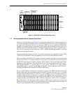
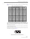
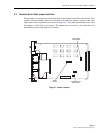
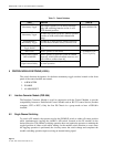
Figure 6-5. Autofallback Jumpers
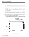
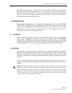
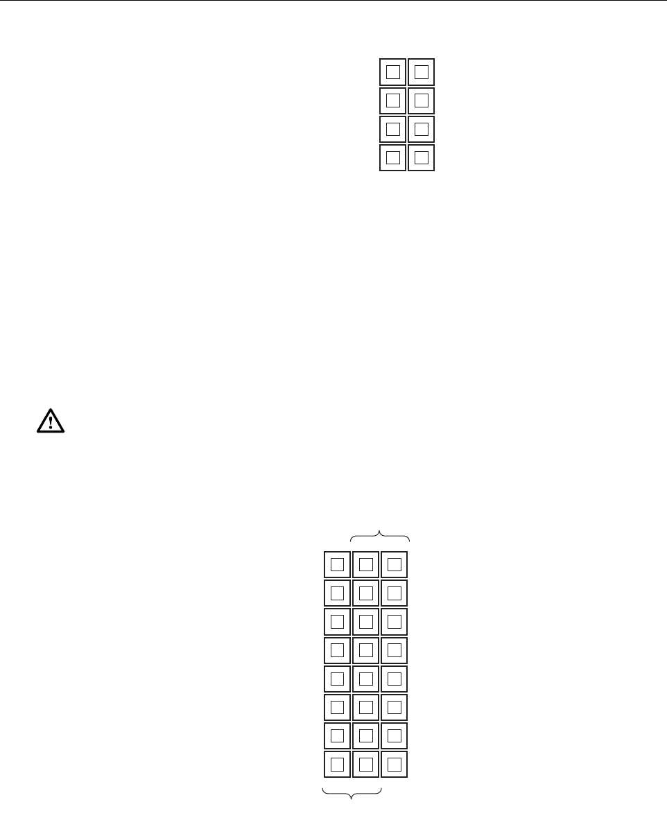
3 CONTROL MODULE REMOTE CONTROL JUMPER INSTALLATION
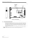
The CM is factory set to configure the 9-pin D-subminiature connector as an RS-422 serial port.
When the dc pulse control bank switching option is selected, the 2
×
8 jumper block must be
installed on the dc pulse control side of the 3
×
8 jumper selections. Refer to Figure 6-6 for
illustration of the Remote Control Jumpers.
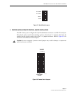
Figure 6-6. Remote Control Jumpers
Caution: Incorrect strapping of remote control jumpers may result in damage to components
and/or inadvertent switching.
1568-A
AUTO SW B
AUTO SW A
INTLK V
STORE
1561-A
DC PULSE
CONTROL
RS-422 SERIAL
CONTROL