


ADCP-50-304 • Issue 19 • June 1999 • Section 7: Operation
Page 7-5
© 1999, ADC Telecommunications, Inc.
6.3 Bank Switching
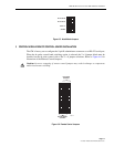
Bank switching is performed by the operator toggling the A/B MASTER switch (located on the
Control Module) to either the A or B position and then toggling the ENABLE (directly below
the A/B MASTER switch) switch (off-center position). This operation causes all of the PS
chassis modules to switch to the channel (A or B) corresponding to the selection of the A/B
MASTER switch. To avoid a slight delay in the switching operation, the A/B MASTER switch
should be held in position (A or B) while toggling the ENABLE switch.
Bank switching starts with module 0 (slot l) and ends with PS chassis module 15 (slot 16). The
individual module A/B switches are disabled while the A/B MASTER switch is toggled in
either the A or B position.
6.4 Reset Alarms
To reset the module alarms, the operator toggles the ALARM RESET switch (located on the
Control Module) to either off-center position. If a constant alarm condition exists, the yellow
LED indicators for each module sensing an alarm remain lit and the audible alarm remains
activated, if enabled. If a constant alarm condition no longer exists, toggling the ALARM RESET
switch extinguishes all of the module alarm LEDs (yellow) and silences the audible alarm.
The alarm reset function clears all the alarm circuits. An individual module alarm circuit may be
selectively reset by touching the two posts on the alarming module.
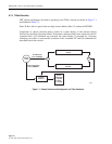
6.5 DC Pulse Control Switching
The PatchSwitch Control Module is capable of Bank switching the PS chassis modules which
perform A/B switching by responding to dc voltage pulses received over the communications
channel from a remote device. In order to enable dc pulse control, the remote control jumper
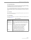
block must be set to the dc pulse control selection. Bank switching via (signal ground), +5V or
–5V to –48V dc to the corresponding lead (see Table 2-2 for pin assignments) for a minimum of
250 msec and should be removed within 1 sec after application since all other switching
functions are disabled during this time.
As with front panel bank switching, all modules in the PS chassis will switch to the channel (A
or B) corresponding to the dc voltage applied per Table 2-2.
Bank switching starts with module 0 (slot 1) and ends with PS module 15 (slot 16). The
individual module A/B switches are disabled while the dc voltage is present.
Note:
If a “switched to” A dc voltage level is applied while a “switched to” B dc voltage
level is active, all modules will switch to the A position but will be restored to the B
position after the “switched to” A signal is removed, provided the “switched to” B signal
remains active.