


ADCP-50-304 • Issue 19 • June 1999 • Section 4: PatchSwitch X.21
Page 4-4
© 1999, ADC Telecommunications, Inc.
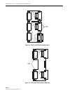
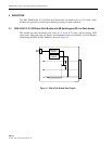
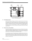
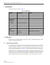
2.4 PSM-83301 X.21 PatchSwitch Module
This module provides monitoring and access to 15 active X.21 leads. A block diagram
representing the PSM-833001 module is shown in Figure 4-4.
Figure 4-4. PSM-833001 Module Block Diagram
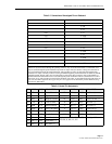
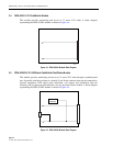
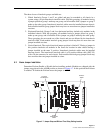
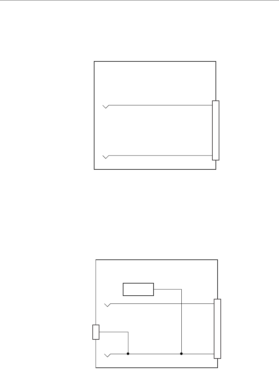
2.5 PSM-832002 X.21 LED/Alarm PatchSwitch Test/Status Module
This module provides monitoring and access to 15 active X.21 leads through a standard patch
port. In parallel with this port there is a female 15-pin D-sub connector that may be connected to
external equipment. LED signal status indication, call request and termination time-out
alarming, and six quiescent state indicators are also provided on this module. A block diagram
representing the PSM-832002 module is shown in Figure 4-5.
Figure 4-5. PSM-832002 Module Block Diagram
1631-A
ALARM
CIRCUITS
1632-A