


ADCP-50-304 • Issue 19 • June 1999 • Section 2: Functional Description
Page 2-6
© 1999, ADC Telecommunications, Inc.
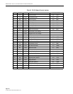
The cable connectors are 9-pin, D-subminiature. Both end-connectors are male. The cable may
be up to 1,000 feet in length. Connector pin assignments are detailed in Table 2-1.
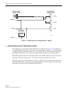
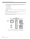
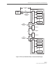
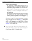
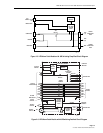
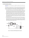
Each PS chassis contains two female 9-pin D-subminiature connectors wired in parallel. A
cable connects one PS chassis to another in daisy-chain fashion. A long cable connects the
remote control device to the first (or last) PS chassis in the chain. Up to 16 PS chassis may be
interconnected via the communications cable to a remote control device.
All transmissions between the PatchSwitch Control Module and the remote control device must
use the ASCII character set. The PS chassis is a DCE device and has the following data
transmission characteristics:
1. Speed of 1200 bits per second
2. Asynchronous transmission
3. Bit-serial ASCII data (8 bit no parity)
4. One Stop bit.
During normal operations, only one (of the possible 16) PS chassis CM may transmit on the
communications channel at one time. When a PS Chassis is selected by the remote control
device, all other PS chassis connected on the same channel are disabled (de-selected). All
manual controls on a CM are always functional.
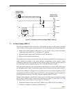
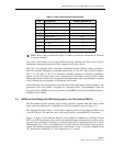
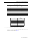
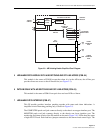
With the CM strapped for dc pulse control, the CM provides capability to bank switch PS chassis
modules by application of 0V (GND), +5V or –5V to –48V dc voltage levels on the 9-pin D-
subminiature connector. The connector pin assignments are detailed in Table 2-2.
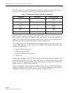
Table 2-1. Communications Channel Connector Pin Assignments
SIGNAL NAME PIN NUMBER DIRECTION OF SIGNAL
TD +
TD –
6
7
Input
Input
RD +
RD –
2
3
Output
Output
CTS +
CTS –
4
5
Output
Output
RTS +
RTS –
8
9
Input
Input
GRD – 1Ground