


ADCP-50-304 • Issue 19 • June 1999 • Section 6: Installation
Page 6-8
© 1999, ADC Telecommunications, Inc.
4 PS MODULE JUMPER INSTALLATION
4.1 Interlock Jumper Installation
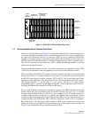
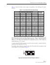
If an interlock option is desired for the system, the proper jumper must be connected in each A/
B Switching Module before it is installed into the chassis. Each A/B Switching Module has five
interlock jumper positions. One jumper position for each of four interlock groups (labeled “1”
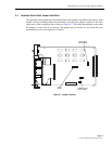
through “4”) and one vertical interlock group (labeled “V” or “Store”). Refer to Figure 6-7 for
the location of the jumpers on the module.
Interlocking is used to protect the user from accidentally switching a common backup piece of
equipment onto two or more different data lines. This is accomplished by allowing only the first
module in that group to switch. The remaining modules remain in the “normal state” or the “A”
position. Modules in the “B” position once switched to “A” will remain in the “A” position.
The three classes of interlock groups available are:
1. Global Interlock: Groups 1 and 2 are global and my be extended to all chassis at an
installation, using an interchassis interlock cable. With this grouping, all modules having a
jumper on group 1 make up one group, and all modules with a jumper on group 2 make up
the other group (providing interchassis cables are installed between chassis).
2. Horizontal Interlock: Groups 3 and 4 are horizontal and they include only modules in the
individual chassis. With this grouping, all modules in a chassis having a jumper on group 3
make up one group, and all modules having a jumper on group 4 make up the other group.
These groupings do not extend out of the chassis and are not affected by the interchassis
cable.
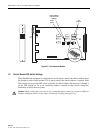
3. Vertical Interlock: The vertical interlock jumper position is labeled with the letter “V”or
the word “Store”. Installing a jumper on this position interlocks all modules in the same
slot location in other chassis having a jumper on the same (V) position. (Providing an
interchassis interlock cable is in place between the chassis). The interchassis interlock
cable is a 20 position ribbon cable with a 20-pin connector for each chassis.
The interlock group jumper block must only have zero or one jumper installed. Never try to
have more than one interlock jumper on any module.
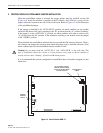
4.2 Alarm Jumper Installation
The alarm jumper must be installed before the module is installed in the chassis. Each module
with the alarming feature has eight alarm jumper positions. Refer to Figure 6-7 for the location
of the jumpers. Select the signal whose absence triggers the alarm, and place the jumper in the
appropriate position. Only one signal may be selected for alarm detection.