


ADCP-50-304 • Issue 19 • June 1999 • Section 2: Functional Description
Page 2-15
© 1999, ADC Telecommunications, Inc.
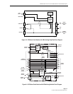
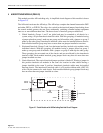
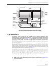
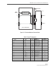
Figure 2-10. LED/Alarm Patch Interface Detailed Circuit Diagram
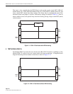
8 TEST MODULE (PSM-12)
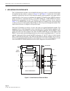
Test Module PSM-12 provides the user with RS-232/V.24 interface capabilities, status
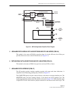
indicators for eight (8) leads and alarm conditions. A simplified block diagram illustrating the
test module connections is shown in Figure 2-11. Two female RS-232/V.24 TEST ports, located
on the rear of the test module, are available for connecting the test equipment. Another female
RS-232/V.24 port and a patch jack are located on the module front panel. All four connectors
are hardwired in parallel.
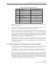
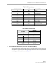
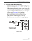
The eight RS-232/V.24 circuit leads having LED indicators are: TD; RD; DCD; SQ; RTS; CTS;
DSR; and DTR. When a monitored circuit lead is active (signal present), the associated LED
indicator turns on (only while the signal is present). The colors and signal definitions for the
applicable LED status indicators are detailed in Table 2-4.
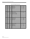
An adjustable alarm circuit with associated LED (ALM), is provided to inform the user when a
preselected alarm condition exists on one of the monitored leads. Each monitored lead has a
jumper connection to the alarm circuit control logic. The alarm is user selectable for any one of
the eight leads. The RS-232/V.24 interface signal leads are defined in Table 2-3. The alarm
circuit control logic supplies the alarm signal to the control unit and an alarm indicator.
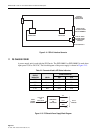
Note:
Except for the A/B switching circuits, the circuit diagram shown in Figure 2-6 is
applicable to PSM-12.
TOGGLE
SWITCH
TD
RD
DCD
SQ
RTS
CTS
DSR
DTR
ALM
ALM
RST
BACKPLANE
ALARM
JUMPER
STATUS
INDICATORS
PIN 2
PIN 3
PIN 8
PIN 21
PIN 4
PIN 5
PIN 6
PIN 7
PIN 20
LOWER
INTERFACE
RS-232C
LEADS
ALARM
CONTROL
MODULE
+5 Vcd
GND
STORE
AUTOMATIC
ALARM
RESET
ALARM
CIRCUIT
CONTROL
LOGIC
OFF
LED
DLY
ROTARY
SWITCH
TOUCH
SWITCH
ALARM
INDICATOR
1615-A