


ADCP-50-304 • Issue 19 • June 1999 • Section 4: PatchSwitch X.21
Page 4-6
© 1999, ADC Telecommunications, Inc.
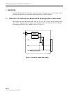
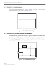
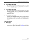
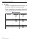
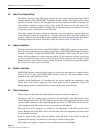
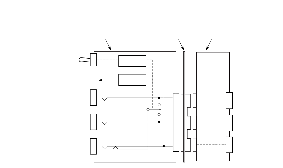
Figure 4-6. A/B Switching Block Diagram
3.2 Switch Module Interlocks
The A/B switch activates the A/B relays. The A/B relays complete the X.21 circuit between the
DCE and either the DTE-A or DTE-B. The relays also switch in the interlock group. A and B
status indicators show the DTE-A and DTE-B selection. Switch Interlocks prevent you from
accidentally switching two modules to the same spare or equipment. The A/B interlock jumper
Groups 1, 2, 3, and 4 allow for connection of each module to one of four different groups. The
A/B interlock Group V allows each module on a chassis to be interlocked vertically with
corresponding modules on any chassis connected with an interchassis interlock cable (catalog
number 4WC-03).
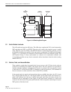
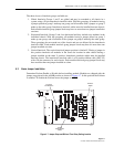
3.3 Monitor, Patch, and Access Modules
These modules contain three front panel jacks for easy access to the X.21 data circuit, and rear
connectors for attaching the module to the digital circuit. The rear connectors are provided to
interface with the computers communications network. A portion of the rear connector is used
to attach the X.21 circuit from the DTE (a computer or front end processor). The remainder of
the rear connector is used to attach the circuit to the DCE (a modem).
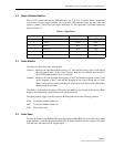
In the normal mode (no patch cords inserted into the top or middle front jacks), the X.21 circuit
has a through-path into and out of the Patch module. In the normal mode, the insertion of a
patch cord connector into the top or middle front panel jack allows the entire circuit to be
monitored with no interruption of the signals. In the patch mode, insertion of a patch cord
connector into the bottom front panel jack breaks the circuit and permits monitoring of only the
DCE portion of the data circuit.
A
B
PATCH
A
B
C
A
C
B
X.21
CHASSIS
BACKPLANE
BACKPLANE
ADAPTER
A/B
SWITCHING
MODULE
1633-A
ALARM
CIRCUITS
SWITCHING
CIRCUIT