


ADCP-50-304 • Issue 19 • June 1999 • Section 2: Functional Description
Page 2-3
© 1999, ADC Telecommunications, Inc.
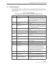
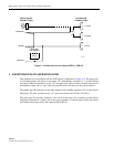
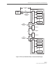
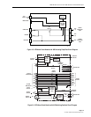
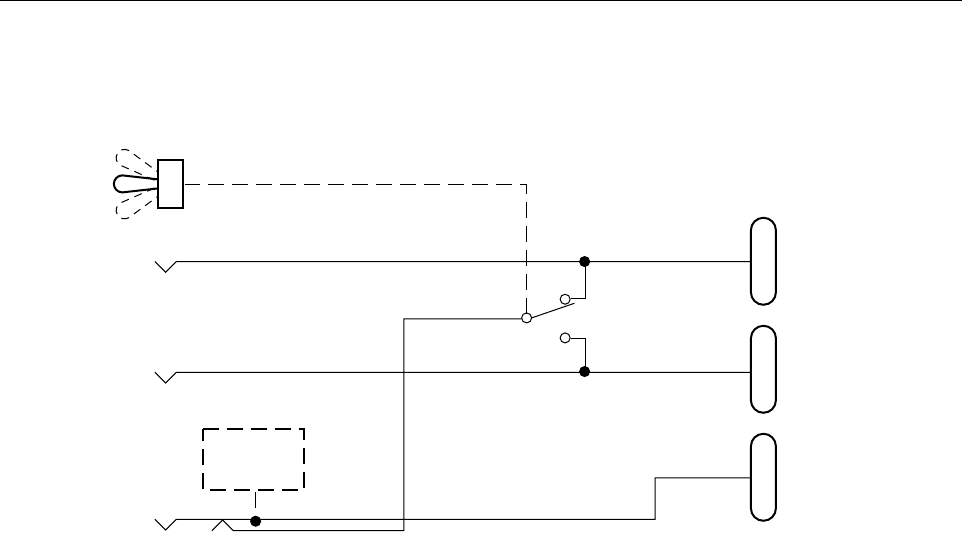
Figure 2-2. PatchSwitch with Off-Line Access (PSM-04, PSM-05)
3.1 PS Control Module (RDM-15)
The PS Control Module (CM) controls the overall manual operations of the modules contained
in the PS chassis. Three toggle switches located on the front panel have the following functions:
1. Bank switch all PS modules to either the “A” or “B” position. That is, switch all modules
at the same time to either the “A” position or “B” position.
2. Enable the bank switch and the individual module A/B switches.
3. Reset all of the modules' alarm circuits.
The audible alarm circuitry is in the CM. It activates when an individual PS module detects an
alarm condition (according to the alarm selection configuration on the module). Alarm
conditions are detected only by modules which contain circuitry. The alarm circuitry must also
be conditioned by proper strapping (jumper) of the individual PS chassis module.
When the alarm condition occurs, the individual module energizes its yellow LED indicator and
the CM audible alarm sounds. The operator toggles the reset switch to reset the alarm circuitry.
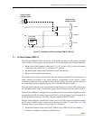
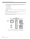
The PS Control Module is equipped with a selectable remote control feature. Depending on the
strap position the CM will either accept serial RS-422 or dc level (pulse) signals through the 9-
pin D-subminiature connector. The CM is shipped strapped for RS-422 control.
With the CM strapped for serial RS-422 remote control, the CM provides an interface between
the PS chassis modules and a remote control device (see Figure 2-3 and Figure 2-4). The
following devices can be used for remote control of a PS chassis.
1. PatchSwitch Remote Control Unit (RCU, PSR-03) (See ADCP-50-302 User Manual.)
2. Terminal or computer (asynchronous ASCII device).
A
B
A
B
A
B
C
J1 DTE-A
J2 DTE-B
J3 DCE
LED/ALARM
ELECTRONICS
(PSM-04
ONLY)
FRONT PANEL
CONNECTIONS
BACKPLANE
CONNECTIONS
1608-A