


ADCP-50-304 • Issue 19 • June 1999 • Section 2: Functional Description
Page 2-16
© 1999, ADC Telecommunications, Inc.
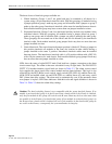
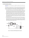
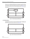
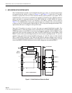
This logic is also controlled by the RST (Reset) touch switch, toggle switch OFF (LED off,
audible alarm off), ALM (LED and audible alarm on), LED (LED on, audible alarm off), and
rotary switch DLY (alarm time delay setting). The alarm may be automatically reset if the
automatic alarm reset jumper is in place. Alarm delay settings are shown in Table 2-5. After an
alarm condition occurs, the operator may reset the circuit by placing a finger on the RST (touch)
switch contacts.
Figure 2-11. PSM-12 Test Module with LED Monitoring
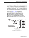
9 TEST MODULE (PSM 13)
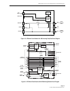
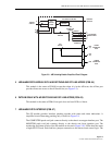
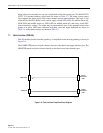
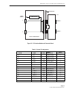
Test Module PSM-13 provides the user with the same RS-232/V.24 interface capabilities as Test
Module PSM-12, except it does not contain status and alarm monitoring. A simplified block
diagram illustrating the test module connections is shown in Figure 2-12.
Figure 2-12. PSM-13 Test Module without LED Monitoring
L
E
D
R
S
2
3
2
(F)
M
O
N
I
T
O
R
R
S
2
3
2
(F)
MONITOR
CIRCUIT
PATCH
JACK
TEST
PORT
TEST
PORT
1616-A
R
S
2
3
2
(F)
R
S
2
3
2
(F)
M
O
N
I
T
O
R
R
S
2
3
2
(F)
PATCH
JACK
TEST
PORT
TEST
PORT
1617-A
R
S
2
3
2
(F)