


ADCP-50-304 • Issue 19 • June 1999 • Section 4: PatchSwitch X.21
Page 4-12
© 1999, ADC Telecommunications, Inc.
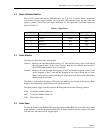
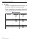
6.3 Alarm Time Delay Setting
Time delay values are fixed. The switch positions are time values ranging from none to 105.9
seconds nominal. The PSM-832002 Test/Status module contains two eight position rotary
switches (A and B Alarm) on the front panel that can be set after the module is installed. All
other modules contain one eight position rotary switch (B Alarm) on the front panel. This
switch can be set after the module is installed. The A alarm time delay (call request) is set using
a 16 position rotary switch located on the PC board.
Time delay settings (8 position switch) are denoted on the front panel by varying length arcs
around the rotary switch, the longer the arc – the greater the time delay. Time delay settings (16
position switch) are denoted on the switch by numbers and letters. Set desired time delay before
installing module in the chassis. Time delay values are listed in Table 4-2 and Table 4-3.
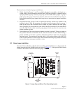
6.4 Adapter Installation
Working at the back of the chassis, install PSO-839001 or PSO-836001 adapters, as appropriate,
into a slot at the right-most vacant position of the chassis. The PSO-839002 adapter is normally
installed in position 17 behind the PSM-832002 Test Module. While facing the back of the
chassis, hold the adapter in a vertical position with the 15-pin connectors towards yourself and
the 25-pin connectors away from you. Place the three 25-pin connectors into the three 25-pin
mating connectors on the chassis and press firmly into place. Using the screws provided, tighten
the connector to assure a good connection.
6.5 Module Installation
PSM-832002 module is installed in the right most chassis slot when chassis is viewed from the
front. If slot 17 is open install PSM-832002 module in this slot. The other modules can be
installed in any of the other chassis slots.
Carefully install PatchSwitch X.21 modules into the chassis making sure connectors on the
bottom edge of the module engage the slots on the mother board as appropriate. Using a #3
Phillips head screwdriver tighten hold down screws on the front of the modules.
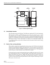
6.6 Cable Connections
The next step is to attach the data communications network to the rear connectors.
The top two rear X.21 connectors are provided for the attachment of the DTE portion of the
circuit. Bring the end of the “B” DTE cable in from one side of the equipment rack and connect
it to the middle connector on the adapter. Bring the end of the “A” DTE cable in from one side
of the equipment rack and connect it to the top connector on the adapter.
The bottom rear X.21 connector is provided for the attachment of the DCE portion of the
circuit. Bring the end of the DCE cable in from the other side of the equipment rack and connect
it to the bottom connector.
Form the cables neatly away from the modules along the back of the chassis towards the
equipment rack upright. Use cable ties as necessary to secure cables in place.
Plug in the power supply or turn power on to establish power for the modules.