


ADCP-50-304 • Issue 19 • June 1999 • Section 2: Functional Description
Page 2-4
© 1999, ADC Telecommunications, Inc.
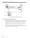
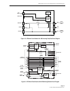
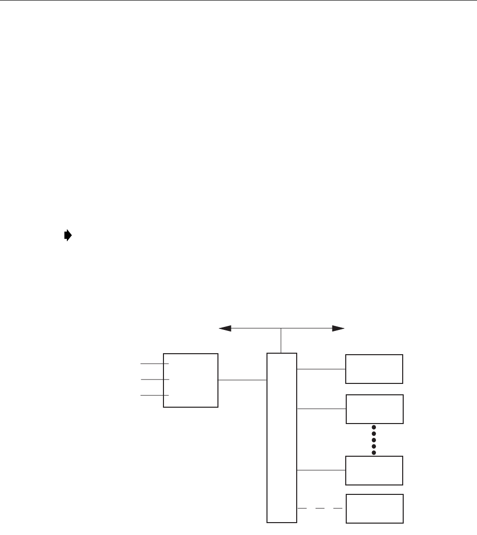
A remote control device can control the operation of up to 16 full PS chassis assemblies (16
modules each) using a dedicated communications channel. This channel has four signals:
1. Transmit Data (TD)
2. Receive Data (RD)
3. Clear-To-Send (CTS)
4. Request-To-Send (CTS)
Each of the above signals has the same function as the corresponding signals defined by the RS-
232 standard.
The communications channel transmission medium is a cable consisting of four twisted wires
within an overall shield. The shield is ground potential.
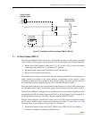
Figure 2-3. Control Module, Simplified Block Diagram (Standard and Remote)
Note:
The electrical characteristics of the communications channel cable (9-wire)
conform to RS-422A/V.11 (X.27) standards.
CONTROL
MODULE*
MODULE 0
SLOT 1
MASTER A/B
ENABLE
RESET
P/S
C
H
A
S
S
I
S
B
A
C
K
P
L
A
N
E
MODULE 1
SLOT 2
MODULE 15
SLOT 16
SLOT 17
P/S MODULES
2 THROUGH 14
(SLOT 3-15)
COMMUNICATIONS
CHANNEL**
TO NEXT P/S CHASSIS
REMOTE
CONTROL DEVICE
* STANDARD
CONTROL OR
REMOTE
CONTROL
** USED ONLY
BY REMOTE
CONTROL
MODULE
SLOT 18
1609-A