


ADCP-50-304 • Issue 19 • June 1999 • Section 2: Functional Description
Page 2-8
© 1999, ADC Telecommunications, Inc.
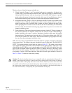
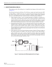
The three classes of interlock groups available are:
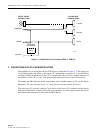
1. Global Interlock: Groups 1 and 2 are global and may be extended to all chassis in a
system, using a 20-pin interchassis interlock cable. With this grouping, all modules having
a jumper placed on group 1 make up one group, and all modules with a jumper on group 2
make up the other group. Interchassis interlock cables must be installed between chassis.
Each module interlock group may have no more than one jumper installed at a time.
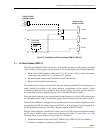
2. Horizontal Interlock: Groups 3 and 4 are horizontal and they include only modules in the
individual chassis. With this grouping, all modules having a jumper placed on group 3
make up one group, and all modules with a jumper on group 4 make up the other group.
These groupings do not extend out of the chassis and are not affected by the interchassis
interlock cable. Each module interlock group jumper block may have no more than one
jumper installed at a time.
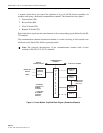
3. Vertical Interlock: The vertical interlock jumper position is labeled V. Placing a jumper in
this position interlocks all modules in the same slot location in other chassis having a
jumper installed on the same V position. Interchassis interlock cables must be installed
between chassis. The interchassis interlock cable is a 20 position ribbon cable (4WC-03)
with a 20-pin connector for each chassis. Each module interlock group jumper block may
have no more than one jumper installed at a time.
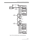
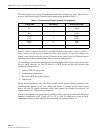
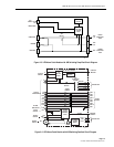
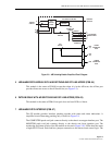
LEDs show the status of eight RS-232 leads. Each lead has a jumper connection to the alarm
circuit control logic. The alarm is thus user selectable for any of eight leads. The EIA RS-232/
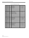
CCITT V.24 modem interface signal leads are shown in Table 2-3. The alarm circuit control
logic supplies the alarm signal to the control module and an alarm indicator. This logic is also
controlled by the RST (Reset) touch switch, toggle switch OFF (LED off, audible alarm off),
ALM (LED and audible alarm on) and LED (LED on, audible alarm off), and rotary switch
DLY (alarm time delay setting). The alarm may be automatically reset if the automatic alarm
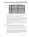
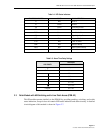
reset jumper is in place. LED status indicators with their color and signal definition is shown in
Table 2-4. Table 2-5 shows the alarm delay settings.
Caution: The bank switching feature is not compatible with the group interlock feature. If no
module in an interlocked group is in the B state when a bank switch to the B state is initiated,
only the first module in this group will switch to the B state. Data may be lost when more than
one module is in the B state of an interlocked group. If one module in an interlocked group is in
the B state when a bank switch is initiated, the rest of the modules in that interlocked group do
not switch to the B state; consequently, the system maintains its integrity
.