


ADCP-50-304 • Issue 19 • June 1999 • Section 6: Installation
Page 6-4
© 1999, ADC Telecommunications, Inc.
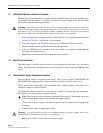
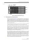
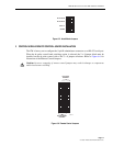
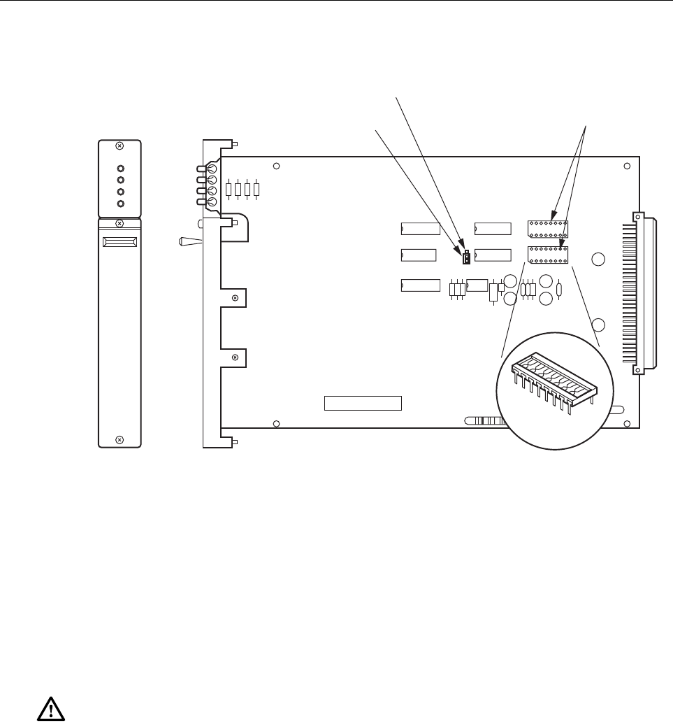
Figure 6-2. Data Converter Module
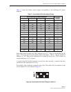
1.6 Control Module DIP Switch Settings
When PatchSwitch equipment is configured for serial remote control, the chassis address must
be selected on each control module. For dc pulse control, the chassis address is ignored. Each
CM contains a four-position DIP switch to identify its chassis address. Bit positions 1 through 4
on the DIP switch are set to an identifying address assigned to that chassis during the
installation of the PS chassis system.
Caution: Make certain that each chassis on a communications channel is assigned a different
(unique) identifying address in the range of 0 through 15 (000
2
through 1111
2
)
.
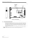
RSP
CMD
SEL
CTL
U3 U1
U5
U4 U6
U2
DTE
DCE
PROGRAMMING
PLUG
BERG
STRAP
DCE/DTE BERG
POST FOR DSR
JUMPER
DIP
SOCKET
1635-A