


ADCP-50-304 • Issue 19 • June 1999 • Section 7: Operation
Page 7-2
© 1999, ADC Telecommunications, Inc.
1 GENERAL
The PS equipment functions in either patching or switching methods of operation. The patching
operations include intrusive monitor and interface while the switching operations are performed
either locally or remotely.
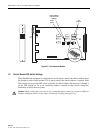
2 PATCHING — IN-LINE ACCESS MODULES
In patching operations, patch cord connections are made through the front of the PS equipment
modules. Those areas to be patched (communications network equipment) are connected to
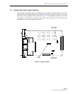
connectors on the rear of the PS equipment chassis. Refer to Figure 6-1 in Section 6 of this manual.
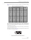
All patch cords for use on this equipment are listed in Table 1-2 in Section 1 of this manual.
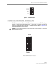
2.1 Monitor Patching
Monitoring patching is performed by inserting a patch cord into the MONITOR jack of a PS
equipment module. This provides a bridge connection to the RS-232/V.24 circuit, and this
connection induces no interruption of the circuit. Now that the data circuit has been accessed,
the other end of the patch cord can be inserted into the jack of an Interface Module that has test
equipment attached to it. This monitor function can also be accomplished by patching a
monitoring device (e.g., data line monitor) directly into the desired MONITOR jack circuit.
2.2 Intrusive Patching
Intrusive patching is used to perform a restoral function on a failed component, to make a
substitution of a different device, or to reroute a communications path. The patching function is
activated by inserting a patch cord into either the COMPUTER or MODEM jacks of a PS
equipment module. This action splits the circuit and routes the signals through the patch cord.
The other end of the patch cord can then be inserted into another jack and in so doing, attach a
different device. For example, it has been determined that a particular circuit has a bad modem.
A patch cord is then inserted into that COMPUTER jack, and the other end of the patch cord is
connected to the jack of a spare modem. This patching function has split the original circuit,
rerouted the computer signals through the patch cord, and finally connected the spare modem to
the original data communications circuit.
Tandem operation of computers and/or modems is not recommended; and consequently, patch
cords should not be used to connect a COMPUTER jack to another COMPUTER jack or
MODEM jack to a MODEM jack.
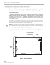
3 PATCHING — OFF-LINE ACCESS MODULES
When the module is in the normal (A) state the upper port provides patch cord access to the
upper “D” subminiature connector on the chassis rear panel, thus providing a “monitor”
function. When the module is in the “B” or “sub" state, this port provides direct test access to
the off-line device.