


ADCP-50-304 • Issue 19 • June 1999 • Section 7: Operation
Page 7-19
© 1999, ADC Telecommunications, Inc.
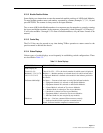
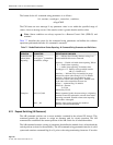
6.21 Reset Alarm Status (IN Command)
The IN (Initialize) command requests the CM to reset the alarm status in all the modules
contained in the selected PS chassis. The IN command string must contain a command flag (#
or $) prior to the string terminating characters. If an echo flag occurs in the IN command string,
the user must issue a GO command before the selected PS chassis resets the alarm reporting
status in the associated modules. When the terminal sends the “IN#CRLF” command, the CM
software resets all modules that are indicating an alarm condition.
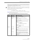
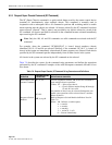
6.22 Enable/Disable Alarm Status Reporting (AL Command)
The AL (ALarm) command enables or disables the alarm status reporting for any one or all
modules in the selected PS chassis. This command enables or disables the appearance of an
alarm condition in the status response from the CM. Actually, the reporting PS chassis may have
an alarm condition, but the software ignores this condition when the disable function is in effect.
The AL command is a software function only, and does not change the state of the hardware
when executed.
The AL command must contain a string of parameters for defining the action (enable or
disable), the type of circuit card, the slot number where the action is to start and the slot number
where the action is to end. The AL command string parameters must be in valid syntax and
contain a command flag (# or $) prior to the string terminating characters. If an echo flag ($)
occurs in the AL command string, the user must issue a GO command before the PS chassis
enables or disables alarm status reporting for the selected module slots. If an execute flag (#) is
contained in the AL command string, the CM executes the AL command string immediately
when it is received.
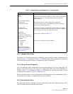
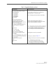
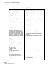
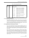
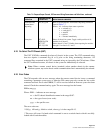
Table 7-6. “SPKxx” Command Status Responses
KEY IN RESPONSE DEFINITIONS OR COMMENTS
SPK01 RDY01 Chassis 01 selected
UP Request status update
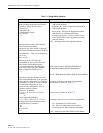
56A31010 5
16
= 01010
2
= Modules l5 and l3 in “A” switch position.
Modules l4 and l2 in “B” switch position.
6
16
= 0110
2
= Modules 11 and 8 in “A” switch position.
Modules l0 and 9 in “B” switch position.
A
16
= 1010
2
= Modules 6 and 4 in “A” switch position.
Modules 7 and 5 in “B” switch position.
3
16
= 0011
2
= Modules 3 and 2 in “A” switch position.
Modules l and 0 in “B” switch position.
1
16
= 0001
2
= Modules 15, l4, and 13 no alarm detected.
Module l2 in alarm.
0
16
= 0000
2
= Modules 11, l0, 9, and 8 no alarm detected.
1
16
= 0001
2
= Modules 7, 6, and 5 no alarm detected.
Module 4 in alarm.
0
16
= 0000
2
= Modules 3, 2, 1, and 0 no alarm detected.