


ADCP-50-304 • Issue 19 • June 1999 • Section 6: Installation
Page 6-6
© 1999, ADC Telecommunications, Inc.
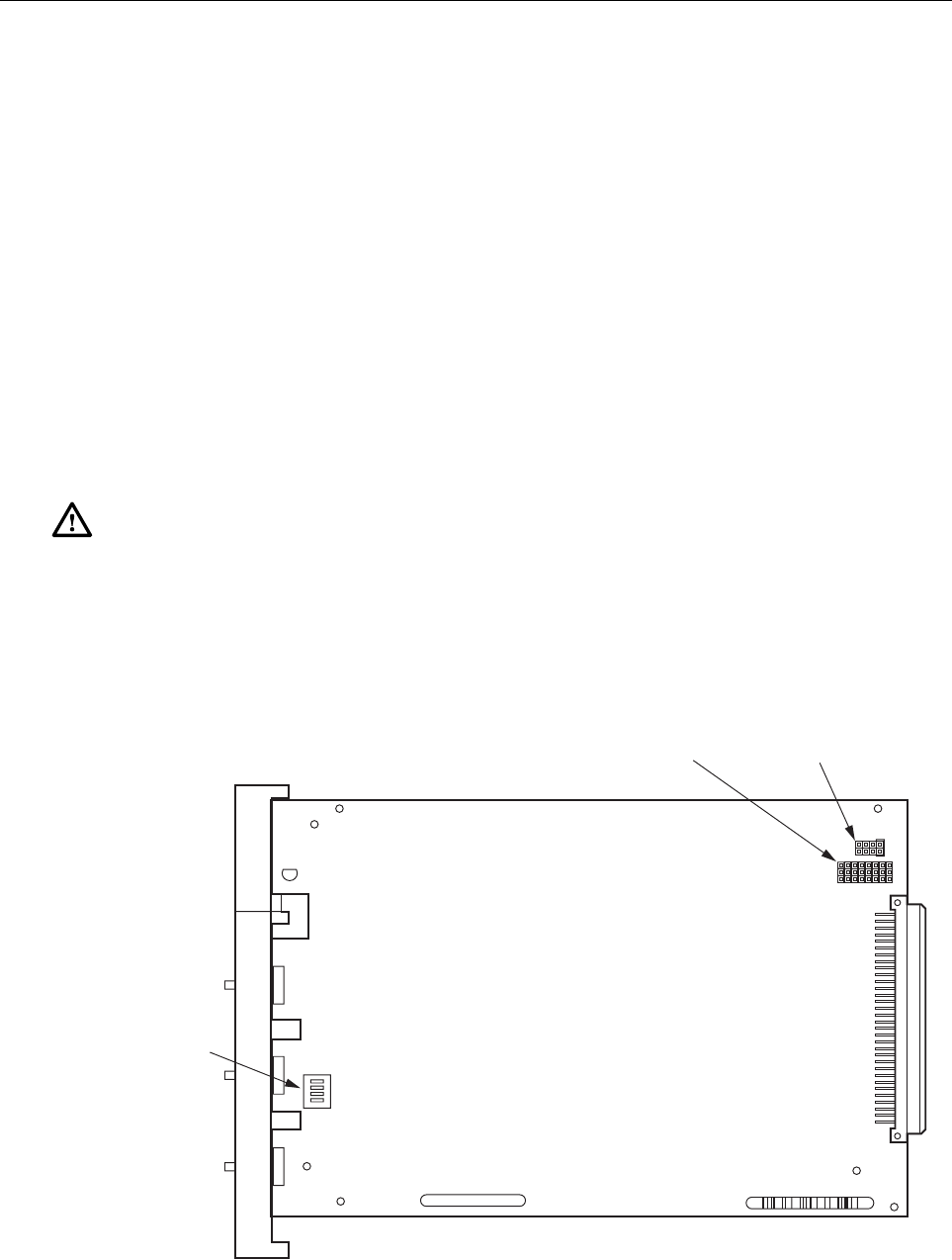
2 CONTROL MODULE AUTOFALLBACK JUMPER INSTALLATION
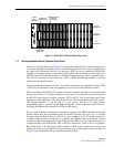
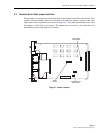
When the autofallback option is selected, the proper jumper must be installed on the CM
(Figure 6-4) before the module is installed in the PS chassis. Each CM has a group of four
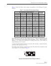
jumper selections located on the side of the circuit board. Refer to Figure 6-5 for an illustration
of the autofallback jumpers.
If the jumper is installed in the “AUTO SW B” position, an alarm condition on any module
within the PS chassis will cause switching to the “B” position from the “A” position. Similarly,
if the jumper is in the “AUTO SW A” position, an alarm condition will cause a switch, to the
“A” position from the “B” position. If the automatic switching is not desired, leave the jumper
in the “STORE” position.
When installed, the autofallback selection does not override the CM software selection. That is,
the software can change the switch position when the jumper strap is installed. However, if the
alarm condition persists, the autofallback feature switches it back.
It is recommended that systems configured for autofallback have all modules strapped for auto
alarm reset.
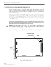
Figure 6-4. Control Module RDM-15
Caution: Do not jumper both the “AUTO SW A” and “AUTO SW B” at the same time. This
type of installation causes the circuits to switch positions every time an alarm condition is
sensed, and can cause “hunting” if both A and B alarm persists
.
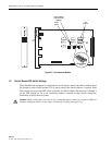
AUTOFALLBACK
JUMPER
RS-422 SERIAL CONTROL
WHEN IN LOWER POSITION,
DC PULSE CONTROL WHEN
IN UPPER POSITION
CHASSIS
ADDRESS
SWITCH
1563-A