


ADCP-50-304 • Issue 19 • June 1999 • Section 6: Installation
Page 6-1
© 1999, ADC Telecommunications, Inc.
SECTION 6: INSTALLATION
1 GENERAL. . . . . . . . . . . . . . . . . . . . . . . . . . . . . . . . . . . . . . . . . . . . . . . . . . . . . . . . . . . . . . . . . . . . . . . . . . . .6-1
1.1 PatchSwitch Chassis Installation (For PatchSwitch V.35 Installation, see Section 3). . . . . . . . . . . . . . . . . . .6-1
1.2 PatchSwitch Module Installation Procedure. . . . . . . . . . . . . . . . . . . . . . . . . . . . . . . . . . . . . . . . . . . . . . .6-2
1.3 Blank Panel Installation . . . . . . . . . . . . . . . . . . . . . . . . . . . . . . . . . . . . . . . . . . . . . . . . . . . . . . . . . . . .6-2
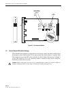
1.4 Chassis Power Supply Connection Procedure . . . . . . . . . . . . . . . . . . . . . . . . . . . . . . . . . . . . . . . . . . . . .6-2
1.5 Communications Network Interface Connections . . . . . . . . . . . . . . . . . . . . . . . . . . . . . . . . . . . . . . . . . . .6-3
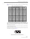
1.6 Control Module DIP Switch Settings. . . . . . . . . . . . . . . . . . . . . . . . . . . . . . . . . . . . . . . . . . . . . . . . . . . .6-4
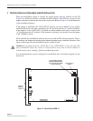
2 CONTROL MODULE AUTOFALLBACK JUMPER INSTALLATION . . . . . . . . . . . . . . . . . . . . . . . . . . . . . . . . . . . . . . . .6-6
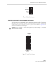
3 CONTROL MODULE REMOTE CONTROL JUMPER INSTALLATION . . . . . . . . . . . . . . . . . . . . . . . . . . . . . . . . . . . . . .6-7
4 PS MODULE JUMPER INSTALLATION . . . . . . . . . . . . . . . . . . . . . . . . . . . . . . . . . . . . . . . . . . . . . . . . . . . . . . . . .6-8
4.1 Interlock Jumper Installation. . . . . . . . . . . . . . . . . . . . . . . . . . . . . . . . . . . . . . . . . . . . . . . . . . . . . . . . .6-8
4.2 Alarm Jumper Installation . . . . . . . . . . . . . . . . . . . . . . . . . . . . . . . . . . . . . . . . . . . . . . . . . . . . . . . . . .6-8
4.3 Automatic Alarm Reset Jumper Installation. . . . . . . . . . . . . . . . . . . . . . . . . . . . . . . . . . . . . . . . . . . . . . .6-9
_________________________________________________________________________________________________________
1 GENERAL
This section contains the information necessary to install the PatchSwitch equipment.
1.1 PatchSwitch Chassis Installation (For PatchSwitch V.35 Installation, see Section 3)
Carefully remove the PatchSwitch chassis from its shipping container and visually inspect the
unit(s) for signs of damage.
The PatchSwitch equipment is normally shipped with the modules installed in the chassis. If the
modules are not contained in the chassis location slots when the shipment is received, perform
the PatchSwitch Modules Installation Procedure. When the chassis is received with the modules
installed, perform the following procedure:
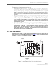
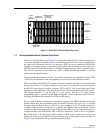
1. Mount the PS chassis in the selected rack space.
2. Secure the chassis to the rack with the appropriate standard hardware.
After each PS chassis is installed, perform the Chassis Power Supply Connection Procedure in
this section of the manual.
Content Page
Warning: To prevent electrical shock, never install PatchSwitch equipment in a wet location or
during a lightning storm. When installing or modifying telephone lines, disconnect lines at the
network interface before working with uninsulated lines or terminals
.
Note:
When PatchSwitch equipment is shipped from the factory, each component and all
associated parts, hardware and accessories are properly packaged according to accepted
practices for transporting via commercial common carrier. Evidence of actual or possible
damage to the equipment, and/or missing parts, should immediately be reported to the
commercial carrier or his agent and notify ADC Telecommunications, Inc.