


ADCP-50-304 • Issue 19 • June 1999 • Section 3: PatchSwitch V.35
Page 3-2
© 1999, ADC Telecommunications, Inc.
2 APPLICATION WITH EXISTING UNITS
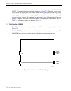
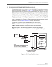
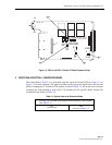
The V.35 PatchSwitch modules can be identified by their gray color. A conversion board must
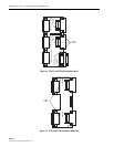
be installed onto the chassis, as shown in Figure 3-1 and Figure 3-2, before the V.35 module
assembly is placed into service. If the conversion boards are not practical, user cables can be
manufactured by local sources to terminate the standard V.35 interface into a DB-25 connector
which can then be connected directly to the RDC-01/PSC-01 or RDC-02/PSC-02 chassis.
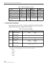
Standard pin arrangements for the V.35 interface to the DB-25 connector can be found in
Table 3-2. As defined further in this guide, optional leads are available on the conversion board
to allow for any six of the normally unused leads on V.35 to be passed through the module. This
option allows the user to configure to his specific needs.
Once the V.35 module is in service, it's use is the same as a regular PatchSwitch module. Test
equipment such as a data line monitor can be connected to the V.35 patch Interface modules or the
LED/Alarm options on the PSM-18 can be used as diagnostic functions with the PSM-17 using
patch cords from one other module to the other. The DTE-A/DTE-B ports on the PSM-16 and
PSM-17 can be used to provide bridge monitor on active circuits or patching into the “C” port can
split the circuit and isolate towards the DCE leaving the “A” and “B” ports to isolate towards
DTE-A and DTE-B respectively. The PSM-18 and PSM-19 interface modules can be used to
attach to test equipment, patch in stand-by spare equipment, to be used as trunking jacks, or in the
case of the PSM-18 LED/ALARM unit it can be used a diagnostic unit with the PSM-17.
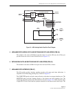
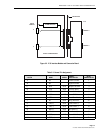
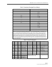
Figure 3-1. Switch Module and Conversion Board
SWITCHING
CIRCUIT
STATUS, DELAY, AND
ALARM CIRCUITS
FRONT LOADING BOARD
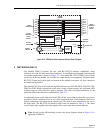
A
B
PATCH
MODULE
A
B
C
REAR BOARD
FEMALE A
MALE C
FEMALE B
V.35
BACKPLANE
1623-A