


ADCP-50-304 • Issue 19 • June 1999 • Section 7: Operation
Page 7-13
© 1999, ADC Telecommunications, Inc.
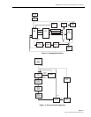
6.19.1 Changing Switch Status
All menus and selections involved in establishing access module switch configurations are
shown in Figure 7-2 and defined in Table 7-4. The Main Menu, Select Operation, immediately
follows the opening status display or completion of a previous operation.
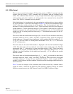
6.19.2 Saving a Current Configuration
Up to five different switch configurations can be stored in memory for use at a future time. All
displays and actions involved in storing of a configuration after it has been established are
shown in Figure 7-3 and defined in Table 7-5. Procedures for selecting and using a stored
configuration are defined in Figure 7-2 and Table 7-4.
The first menu in saving a current configuration is Select Operation, which immediately follows
the opening status display or completion of a previous operation.
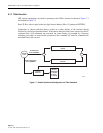
6.19.3 Select Operation Menu
The main menu used for establishing switch configurations is the Select Operation Menu. This
is the first menu displayed after the status display.
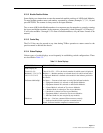
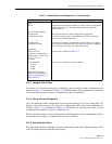
Table 7-3. Chassis Selection and Configuration via TLKxx Command
ACTION DISPLAY DISPLAY DEFINITION
Enter:
TLKxx Request to talk with chassis number xx, with xx equal to any chassis
number from 00 to 15. (Two digits must always be entered for
chassis number.)
Entry of TLKxx displays:
GS application
xxxxxxxxxxx on-line
or
GS application
xxxxxxxxxxx failed
The selected chassis has been configured for Application
xxxxxxxxxx (name of up to eleven characters). This is displayed
only after use of the GS selection.
An attempt was made to configure the selected chassis for Applica-
tion xxxxxxxxxxx, however the chassis was not correctly configured.
This is displayed only after use of the GS selection.
followed by:
Chassis No. XX
xxxxxxxxxxx Application
Module # 0 l 2 3 4 5 6 7 8 9
10 11 12 13 14 15
Sw Status
Switch status as defined in
Table 7-2
.
Select Operation
l. Switch
2. Setup
3. Status
Allows entry of switch and setup conditions.
Enter switch and setup
conditions as described in
Figure 7-2
and
Figure 7-3
and in
Table 7-4
.