


ADCP-50-304 • Issue 19 • June 1999 • Section 4: PatchSwitch X.21
Page 4-8
© 1999, ADC Telecommunications, Inc.
3.7 Alarm Time Delay
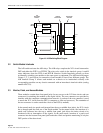
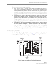
The PSM-832002 Test/Status module contains two eight position rotary switches on the front
panel. One for the A alarm delay and one for the B alarm delay. All other modules contain one
eight position rotary switch on the front panel. This switch is used to set the B alarm delay. The
A alarm time delay is set using a 16 position rotary switch located on the PC board.
Time delay values are fixed. The switch positions are time values ranging from none to 105.9
sec. nominal. Time delay settings (8 position switch) are denoted on the front panel by varying
length arcs around the rotary switch, the longer the arc — the greater the time delay. Time delay
settings (16 position switch) are denoted on the switch by numbers and letters. Time delay
values are listed in Table 4-2 and Table 4-3.
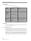
Table 4-2. A Alarm Time Delay Settings
SWITCH POSITION
TIME DELAY
PSM-832002 MODULE OTHER ALARM MODULES
0 None None
1 0.9 sec 1.9 sec
2 1.9 sec 7.9 sec
3 3.9 sec 9.9 sec
4 7.9 sec 31.9 sec
5 15.9 sec 33.9 sec
6 31.9 sec 39.9 sec
7 63.9 sec 41.9 sec
8 — 63.9 sec
9 — 65.9 sec
A — 71.9 sec
B — 73.9 sec
C — 95.9 sec
D — 97.9 sec
E — 103.9 sec
F — 105.9 sec