Cajun P550/P880/P882 Switch User Guide
7-1
7
Configuring Redundancy
Options
Overview
The following information and procedures are provided in this
chapter and are common to both layer 2 and layer 3 module
configuration:
■ Configuring Redundant Hardware
■ Installing Redundant Hardware
■ Enabling Redundant Hardware
■ Configuring a Redundant CPU
Configuring Redundant Hardware
All three switches (layer 2 and layer 3 models) provide a redundant
backplane to ensure that should a supervisor module or a fabric
element fail, it will continue to route data properly. The redundant
components are available as separate options.
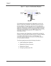
When the redundant controller and element are installed, the
backplane consists of the following parts (Figure7-1):
■ One Primary Controller
■ One Redundant Controller
■ Six Primary elements
■ One Redundant element


