Appendix E: Indicators
239
Appendix E: Indicators
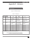
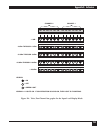
A6 A5 A4 A3 A2 A1AT BO
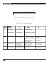
Figure E-1. CCM Indicator Positions.
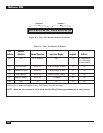
CCM LED Indicator
Indicator Definition Off Flashing On
AT Active Mode Indicates a fault or The unit is in a loopback Normal operation
test condition test mode
BO Buffer Overflow Buffer utilization is Buffer utilization Data has been lost
normal exceeding 87% because of a buffer
overflow
A1 Port A1 Error-free data is High error rate on link Receiving own transmit
passing through or synchronization data; modem is in
the link has been lost with the loopback
remote unit on the link
A2* Port A2 No data activity Data activity Data activity
A3* Port A3 No data activity Data activity Data activity
A4* Port A4 No data activity Data activity Data activity
A5* Port A5 No data activity Data activity Data activity
A6* Port A6 No data activity Data activity Data activity
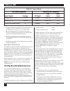
* If configured as a link, the indicator values are the same as for A1.
NOTE: The indicator on a force-connected sync port using either
Fast Packet or TDM protocols will remain on continuously.
Table E-1. CCM Indicators.


