CHAPTER 4: Base-Unit Installation
37
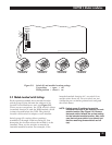
4.6 Identify the Module Locations and
Channel Numbers
MODULE LOCATION AND NOMENCLATURE
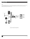
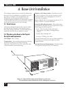
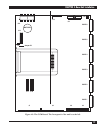
There are five chassis positions available for
modules in the Multiserver 5000. These are
identified from bottom to top as module locations
A through E.
• The Communications Control Module (CCM) is
always in module location A.
• A space is reserved below the CCM for the
optional NMS module. Its module location
is “$.” Note that there is no “$” printed on the
rear-panel of the Multiserver 5000.
• Optional modules can fill module locations B
through E.
C
HANNEL LOCATION AND NOMENCLATURE
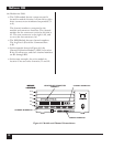
Channel numbers are assigned to all the ports on
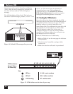
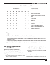
Table 4-1. CCM Indicator LEDs
INDICATOR STATUS EQUIPMENT STATUS
AT BO A6 A5 A4 A3 A2 A1
10 XXXX XX
1
Normal equipment status
0 0 1 0 0 0 0 0 ROM Test Failure (CommPak cartridge
failure)
0 0 0 0 0 0 0 1 CMOS Failure
2
0 0 0 0 0 0 1 0 Battery low
3
0 1 1 0 0 0 0 0 RAM Failure in CommPak cartridge
1 0 1 0 1 0 1 0 Parity error
1 1 1 1 1 1 1 1 CommPak cartridge not installed
properly or defective Multiserver unit
0 1 0 0 0 0 0 0 RAM Test Failure (CCM)
KEY
0 = LED off
1 = LED on
X = LED can be off or on. This will change as the status of the port activity changes.
1
If A1 is configured as a link, it blinks on power-up with no established link. (The default setting is for A1 to be
configured as a link.)
2
System can still operate with CMOS failure. All configuration data has been lost in the affected CMOS section,
and default values have been supplied.
3
System can still operate with a low battery. Configuration data may be lost if the Multiserver loses power.


