Multiserver 5000
60
7.1 Overview
This chapter discusses setting up your Multiserver
network before it is installed in remote locations.
Configuring and testing your network in one
location before its final installation will alleviate
many problems that would result from not having a
Network Manager at each of your remote sites.
The term “Bench Configuration” means setting up
your Multiserver network in one location (a bench
in a lab, for instance), then configuring and testing
the components to make sure they are operating as
they should.
If you are able to complete the configuration
process at your local site, the only responsibilities
for the technician at the remote site will be
attaching cables and plugging in the Multiserver.
K
EY TO EXAMPLES AND ILLUSTRATIONS:
This chapter has a number of illustrations of the
Multiserver’s back-panel and cables that attach to it.
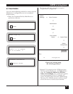
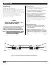
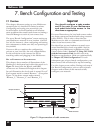
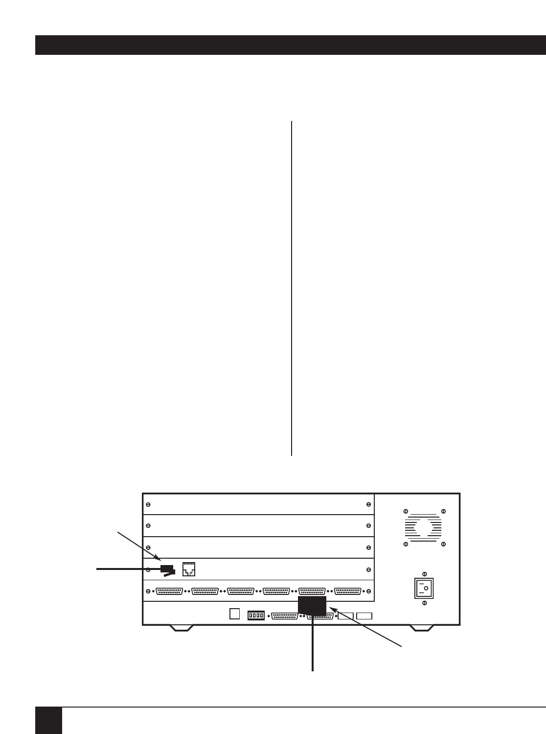
Figure 7-1 shows how the RJ-style and DB25
connectors are illustrated throughout this chapter.
In each illustration the local node is named “Local.”
Each remote node is named “Remote.” (Exception:
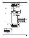
Figure 7-2 has three remote nodes named
“Remote_1,” “Remote_2,” and “Remote_3.”)
Important
You should configure a node number
and ID for each of your Multiservers
and substitute those names in the
directions as appropriate.
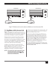
For most illustrations, the local and remote nodes
are shown connected back-to-back using crossover
cable (EZ423). This is only to show that the
Multiservers are able to communicate with each
other via an interconnect link.
You should set up your hardware to match your
actual installation as closely as possible. Start by
setting up your Multiserver-to-Multiserver links
(interconnect links). Section 7.2, Using CSU/DSUs
with the Interconnect Link, should cover most
Multiserver applications. Links are explained fully
in Chapter 8.0, Link Configuration. For each
subsequent part of your bench configuration, your
interconnect link will already be up and running.
Use this chapter as an outline. During each step of
the Bench Configuration, refer to other relevant
chapters and sections of this manual to fully
configure your network.
7. Bench Configuration and Testing
12 456
A
B
C
D
E
3
Figure 7-1. Representations of cable connectors.
RJ-style connectors
DB25 connectors


