Multiserver 5000
46
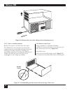
5.5.4 REMOVE SPACERS
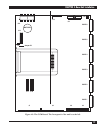
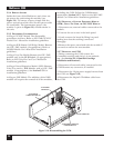
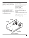
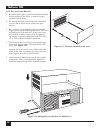
Inside the front of the Multiserver unit, there are
six spacers for positioning the modules (see
Figure 5-9). To remove a spacer, simply slide the
spacer up and out of the unit. Set the spacers aside
for reassembly. The bottom-most spacer (the
number 1 spacer in Figure 5-9) should remain in
the unit.
5.5.5 D
ISASSEMBLY CONSIDERATIONS
Adding a CSU/DSU Module. The disassembly
procedures end here. Refer to MS1 56K CSU/DSU
Module User’s Manual for installation guidelines.
Adding an RLB (Remote LAN Bridge) Module. Remove
the CSU/DSU module (if appropriate). Refer to
MS RLB Module User’s Manual for installation
guidelines.
Adding a Voice/Fax Module. Remove the CSU/DSU
module and/or the RLB Module (if appropriate).
Refer to MS1 Voice/Fax Card User’s Manual for
installation guidelines.
Adding a Channel Expansion Module (CEM). Remove
Voice/Fax card(s), RLB Module, and/or CSU/DSU
module (if appropriate). See Section 5.7.1 for
installation guidelines.
Adding an NMS Module. The addition of the NMS
module will require the removal of all the modules,
including the CCM. Follow the CCM Removal
instructions (Section 5.5.7). Refer to the MS1 NMS
Module User’s Manual for installation guidelines.
5.5.6 R
EMOVING A CHANNEL EXPANSION MODULE
(CEM), VOICE/FAX CARD, OR CSU/DSU MODULE
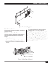
1. Disconnect any external cables connected to the
module.
2. Unscrew the two screws in the back panel.
3. Gently remove the board by lifting it up and
making sure that the stacking connectors
disengage.
4. Remove the spacer associated with the module if
you need to remove the next module.
5.5.7 REMOVING THE CCM
1. Before removing the CCM, remove the
CommPak cartridge and place it in an antistatic
bag. (See Section 4.2, CommPak Cartridge
Installation and Removal.)
2. Disconnect all external cables \connected to the
CCM. Remove any converters, if installed.
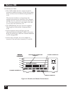
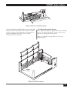
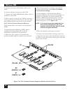
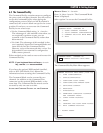
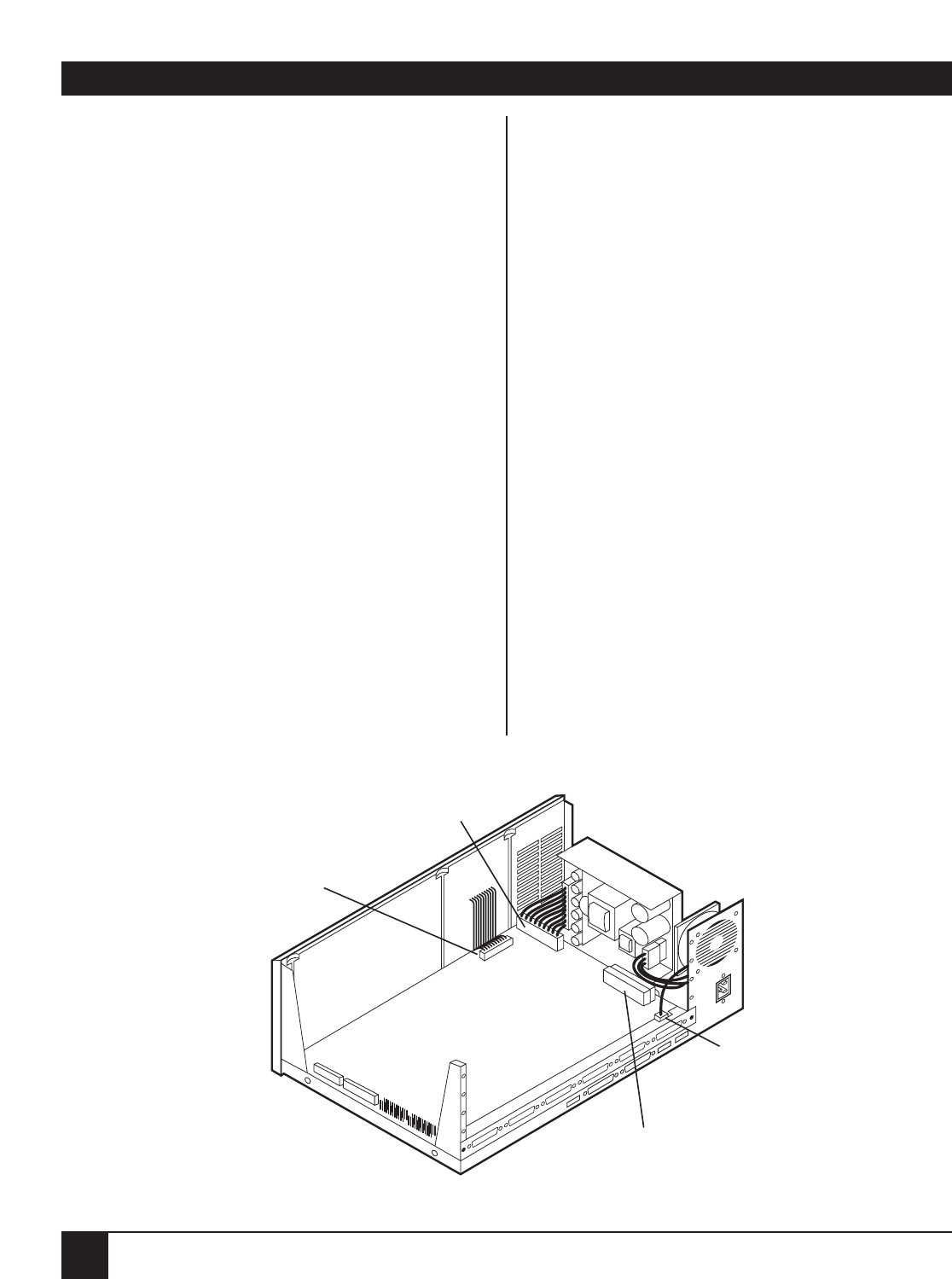
3. Disconnect the 12-pin power supply harness from
the CCM (see Figure 5-10).
4. Disconnect the 26-pin LCD ribbon cable from
the CCM.
26-PIN RIBBON
CONNECTOR FROM LCD
12-PIN POWER
CONNECTOR
34-PIN RIBBON CONNECTOR
FROM NMS MODULE
FAN CONNECTOR
Figure 5-10. Disassembling the CCM.


