Multiserver 5000
64
7.4 The Sync Data Channel
Because of the myriad of different protocol and
equipment combinations available for sync data
channels, there is no simple test that will ensure
your sync application will run smoothly. You will
need to complete data-channel configuration and
then test your specific application. The equipment
at your local site must be able to emulate the
equipment at your remote site for you to be
able to include sync data channels in your Bench
Configuration process.
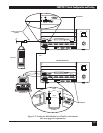
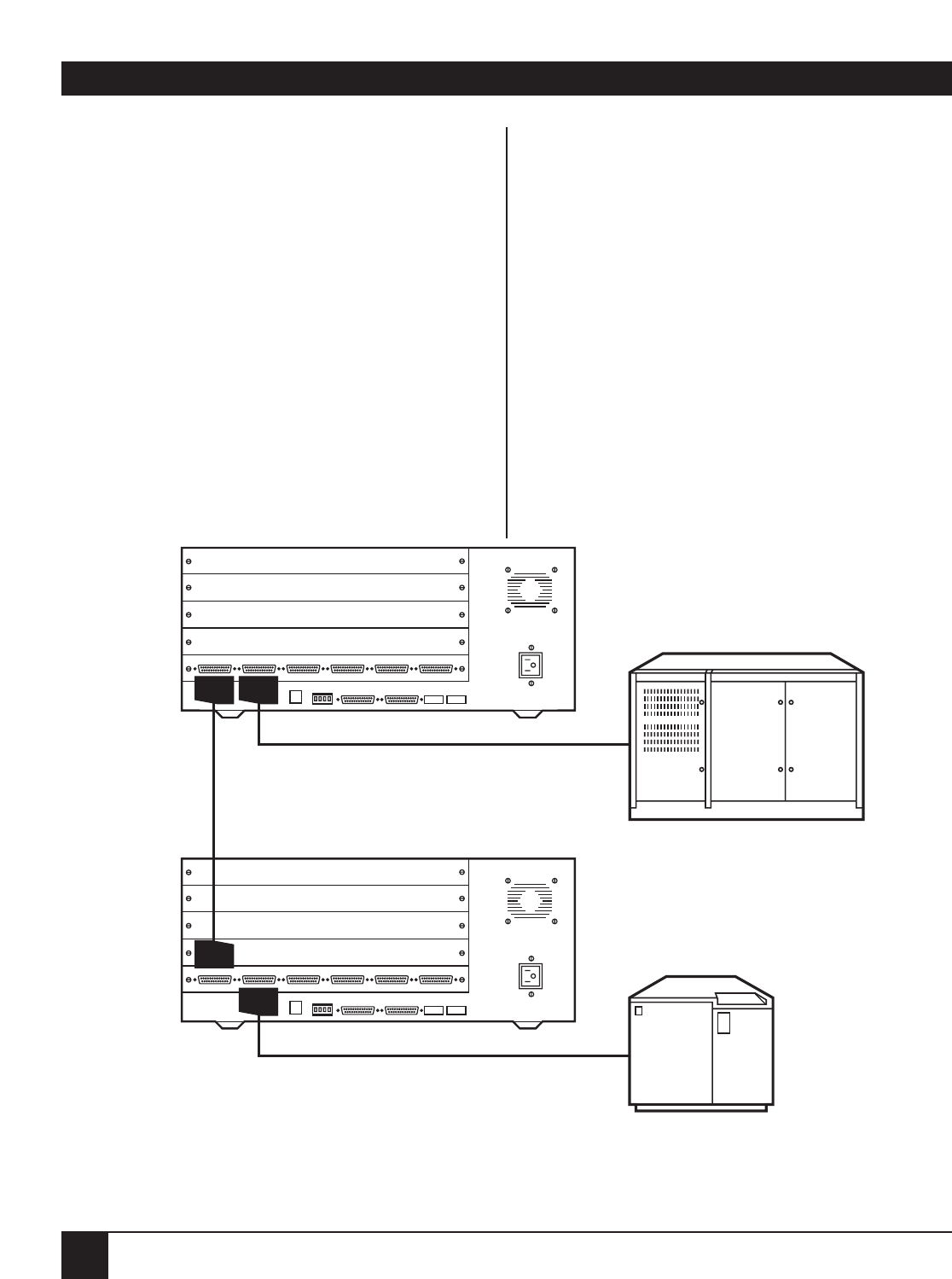
Figure 7-4 shows a typical sync application: a
mainframe at the headquarters and a remotely
located controller. Some companies have a lab with
an extra controller for program-testing purposes. In
this case, you can include the sync channel in your
Bench Configuration.
In the illustration below, port A2 on each of the
Multiservers is configured for synchronous
operation. The correct protocol for each device
must be chosen and the channels must then be
force-connected.
See Section 9.2, Synchronous Channels, for more
information on configuring sync data channels. See
Section 10.1, Switching Control, and Section 10.4,
Synchronous Connections, for more information on
force-connecting two synchronous channels.
Attempt to pass data between the two devices to
verify that both sync channels are compatibly
configured.
12 456
A
B
C
D
E
3
12 456
A
B
C
D
E
3
Straight-Through Male-to-Male Cable (EZ422)
or
Straight-Through Male-to-Female Cable (EDN16C-M/F)
Straight-Through Male-to-Male Cable (EZ422)
or
Straight-Through Male-to-Female Cable (EDN16C-M/F)
EZ423
Mainframe
(DTE configuration,
DB25 connectors)
Controller
(DTE configuration,
DB25 connectors)
Figure 7-4. Bench Configuration for a Sync Data Channel.


