


14-3
Cisco 10000 Series Router Software Configuration Guide
OL-2226-23
Chapter 14 Configuring Automatic Protection Switching
Multirouter Automatic Protection Switching
Restrictions for MR-APS
In Cisco IOS Releases 12.3(7)XI2 and 12.2(28)SB, MR-APS is supported for the following line cards:
• 4-Port OC3/STM-1 ATM line card
• 1-Port OC-12 ATM line card
• 1-Port Channelized OC-12/STM-4 line card
• 4-Port Channelized OC-3/STM-1 line card
In Cisco IOS Release 12.0(26)S, MR-APS is also supported for the following line cards:
• 6-Port OC-3/STM-1 Packet over SONET line card
• 1-Port OC-12 Packet over SONET line card
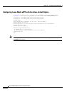
Configuration Tasks for MR-APS
To configure the MR-APS feature, perform the following tasks:
• Configuring MR-APS on Unchannelized Line Cards, page 14-3
• Configuring MR-APS on Channelized Line Cards, page 14-4
• Configuring MR-APS with Static Routes, page 14-5
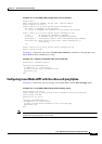
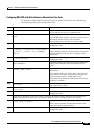
Configuring MR-APS on Unchannelized Line Cards
To configure MR-APS on unchannelized line cards, enter the following commands beginning in global
configuration mode.
Command Purpose
Step 1
Router(config)# redundancy
Enters redundancy configuration mode, which allows you
to associate two line cards as a redundant pair.
Step 2
Router(config-r)# associate slot slot-one
mr-aps
Logically associates slots for APS processor redundancy.
To allow MR-APS to operate, you must associate a slot on
the working interface of one router and with a
corresponding protect interface on a second router.
Step 3
Router(config-r)# exit
Exits redundancy configuration mode and returns to global
configuration mode.
Step 4
Router(config)# interface type number
Specifies the interface type and number. Enters interface
configuration mode.
Step 5
Router(config-if)# aps group group-number
Permits more than one APS protect and working interface
to be supported on a router.
Step 6
Router(config-if)# aps working circuit-number
Configures an interface as a working interface.
Step 7
Router(config-if)# exit
Exits interface configuration mode and returns to global
configuration mode.
Step 8
Repeat steps 1 through 5 on the second router to configure the protect interface. Substitute the appropriate slot
numbers, interface types, and interface numbers. After you complete step 5, go to step 9.