


21-29
Cisco 10000 Series Router Software Configuration Guide
OL-2226-23
Chapter 21 Configuring L2VPN Interworking
ATM to Frame Relay—Routed Interworking
frame-relay intf-type dce
frame-relay interface-dlci 100 switched
connect atm-dlci atm 2/0/0 0/200 serial 2/0/0:1 100 interworking ip
AToM
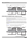
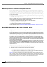
Figure 21-9 illustrates different AToM configurations. This section explains the FR DLCI to ATM AAL5
configurations and provides examples:
FR DLCI to ATM AAL5
To configure the FR DLCI to ATM AAL5 feature on a PE1 router, use the following steps:
1. config t
2. mpls label protocol ldp
3. interface Loopback<name>
4. ip address local-ip-address local-mask
5. pseudowire-class name
6. encapsulation mpls
7. interworking ip
8. interface atm slot/subslot/port
9. pvc vpi/vci l2transport
10. encapsulation aal5snap
11. xconnect remote-ip-address vc-id pw-class name
To configure the FR DLCI to ATM AAL5 feature on a PE2 router, use the following steps:
1. config t
2. mpls label protocol ldp
3. interface Loopback<name>
4. ip address local-ip-address local-mask
5. pseudowire-class name
6. encapsulation mpls
7. interworking ip
8. frame-relay switching
9. interface serial slot/subslot/port[:channel | .channel]
10. encapsulation frame-relay
11. frame-relay intf-type dce
12. frame-relay interface-dlci DLCI switched
13. connect mpls serial slot/subslot/port[:channel | .channel] DLCI l2transport
14. xconnect remote-ip-address vc-id pw-class name
The following example shows how to configure the FR DLCI to ATM AAL5 feature on a PE1 router: