


21-28
Cisco 10000 Series Router Software Configuration Guide
OL-2226-23
Chapter 21 Configuring L2VPN Interworking
ATM to Frame Relay—Routed Interworking
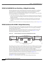
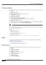
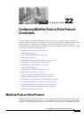
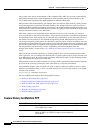
Figure 21-17 ATM to Frame Relay Routed Interworking
Configuration Tasks and Examples
This section describes configuration tasks for and examples of two L2VPN technology solutions
• Local Switching
• ATo M
Local Switching
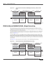
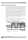
Figure 21-8 shows LS configurations. This section explains LS configuration of the ATM AAL5 to FR
DLCI feature and provides examples.
ATM AAL5 to FR DLCI
To configure the ATM AAL5 to FR DLCI feature on a router, use the following steps:
1. config t
2. interface atm slot/subslot/port
3. pvc vpi/vci l2transport
4. encapsulation aal5snap
5. interface serial slot/subslot/port[:channel | .channel]
6. encapsulation frame-relay
7. frame-relay interface-dlci DLCI switched
8. connect connection-name atm slot/subslot/port vpi/vci serial slot/subslot/port[:channel |
.channel] interworking ip
The following example shows how to configure the ATM AAL5 to FR DLCI feature on a router:
config t
interface atm 2/0/0
pvc 0/200 l2transport
encapsulation aal5snap
frame-relay switching
interface serial 2/0/0:1
encapsulation frame-relay
277387
Bridged frames or
IP packets or Other
payload types
Bridged frames or
IP packets or Other
payload types
ATM Link
FR Link
Tunnel LSP
MPoMPLS
P Router
P Router
P Router
PE
PE
ATM CE
MPLS Network
ATM to FR Interworking
FR CE