


20-44
Cisco 10000 Series Router Software Configuration Guide
OL-2226-23
Chapter 20 Configuring L2 Virtual Private Networks
Configuration Example—Frame Relay over MPLS
Configuration Example—Frame Relay over MPLS
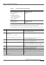
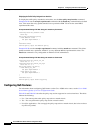
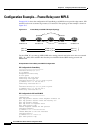
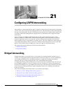
Example 20-31 shows the configuration of Frame Relay over MPLS on two provider edge routers, PE1
and PE2, and on two customer edge routers, CE1 and CE2. The topology for the example is shown in
Figure 20-7.
Figure 20-7 Frame Relay over MPLS Example Topology
For the AToM VCs to come up, MPLS/LDP and a routing protocol need to be run in the core network
(PE1---P----PE2). PE1 and PE2 show that they are enabled with the OSPF routing protocol and
MPLS/LDP.
Example 20-31 Frame Relay over MPLS Configuration
CE1 Configuration for Frame Relay
================================
interface Serial8/0/0.1/1:0
no ip address
encapsulation frame-relay
no fair-queue
frame-relay lmi-type q933a
frame-relay intf-type dce
interface Serial8/0/0.1/1:0.1 point-to-point
ip address 192.1.1.1 255.255.255.0
frame-relay interface-dlci 17
!
interface Serial8/0/0.1/1:0.2 point-to-point
ip address 192.1.2.1 255.255.255.0
frame-relay interface-dlci 18
PE1 Configuration for LDP and AToM VC
==================================
!Enabling LDP
mpls ldp graceful-restart timers neighbor-liveness 300
mpls ldp graceful-restart timers max-recovery 600
mpls ldp graceful-restart
mpls ldp router-id Loopback0 force
mpls label protocol ldp
!Define Loopback address for LDP protocol
interface Loopback0
ip address 1.1.1.1 255.255.255.255
!Enable MPLS/LDP on the core interface
interface POS4/0/0
ip address 50.0.0.1 255.0.0.0
mpls label protocol ldp
143801
CE1 PE1
P
PE2 CE2
ser8/0/0/1:0 ser8/0/0/1:0
(dlci=17)
(dlci=18)
(dlci=17)
(dlci=18)
AToM vc_id =1
AToM vc_id =2
ser7/0/0/1:0 ser7/0/0/1:0
pos4/0/0
pos4/0/0