


20-31
Cisco 10000 Series Router Software Configuration Guide
OL-2226-23
Chapter 20 Configuring L2 Virtual Private Networks
Configuration Tasks for L2VPN
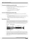
DLCI-to-DLCI Connections
If DLCI-to-DLCI connections are configured, LMI runs locally on the Frame Relay ports between the
PE and CE devices.
• CE1 sends an active status to PE1 if the PVC for CE1 is available. If CE1 is a switch, LMI checks
that the PVC is available from CE1 to the user device attached to CE1.
• PE1 sends an active status to CE1 if the following conditions are met:
–
A PVC for PE1 is available.
–
PE1 received an MPLS label from the remote PE router.
–
An MPLS tunnel label exists between PE1 and the remote PE router.
For DTE/DCE configurations, the following LMI behavior exists:
The Frame Relay device accessing the network (DTE) does not report PVC status. Only the network
device (DCE) or NNI can report status. Therefore, if a problem exists on the DTE side, the DCE is not
aware of the problem.
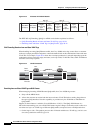
Port-to-Port Connections
If port-to-port connections are configured, the PE routers do not participate in the LMI status-checking
procedures. LMI operates between the CE routers only. The CE routers must be configured as DCE-DTE
or NNI-NNI.
For information about LMI, including configuration instructions, see the “Configuring the LMI” section
of the Configuring Frame Relay document.
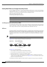
Configuring Frame Relay-to-Frame Relay Local Switching
Frame Relay switching is a means of switching packets based upon the data link connection identifier
(DLCI), which can be looked upon as the Frame Relay equivalent of a MAC address. You perform the
switching by configuring your router or access server as a Frame Relay network. There are two parts to
a Frame Relay network: the Frame Relay data terminal equipment (DTE) (the router or access server)
and the Frame Relay data communications equipment (DCE) switch.
Local switching allows you to switch Layer 2 data between two interfaces of the same type for example,
ATM-to-ATM, or Frame-Relay-to-Frame-Relay.
For background information about Frame-Relay-to-Frame-Relay Local Switching, see the Distributed
Frame Relay Switching feature guide.
You can switch between virtual circuits on the same port, as detailed in the “Configuring Frame Relay
Same-Port Switching” section on page 20-33.
The following channelized line cards are supported for the Cisco 10000 series routers:
• 1-port channelized OC-12/STM-4
• 4-port channelized OC-3/STM-1
• 6-port channelized T3
• 24-port channelized E1/T1
The following packet over SONET line cards are supported for the Cisco 10000 series routers:
• 1-port OC-12 Packet over SONET
• 1-port OC-48/STM-16 Packet over SONET
• 6-port OC-3/STM-1 Packet over SONET