


22-39
Cisco 10000 Series Router Software Configuration Guide
OL-2226-23
Chapter 22 Configuring Multilink Point-to-Point Protocol Connections
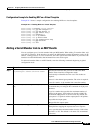
Configuration Examples for Configuring MLP
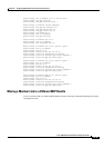
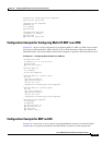
encapsulation aal5mux ppp Virtual-Template1
ppp multilink group 10001
interface Virtual-Template1
bandwidth 512
no ip address
ppp multilink
interface Multilink 10001
ip address <ip address>
ppp multilink
ppp multilink group 10001
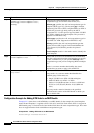
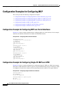
Configuration Example for Configuring Multi-VC MLP over ATM
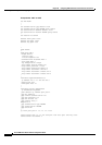
Example 22-7 shows a sample configuration for configuring Multi-VC MLP over ATM. In the example,
PVC 0/36 on ATM subinterface 5/0/0.3 and PVC 0/37 on ATM subinterface 5/0/0.4 are added to the
Multilink2 bundle. The virtual template named Virtual-Template1 is applied to PVC 0/36 and PVC
0/37.
Example 22-7 Configuring Multi-VC MLP over ATM VCs
interface Multilink2
ip address 100.1.2.1 255.255.255.0
ppp multilink
ppp multilink group 2
!
interface ATM5/0/0
no ip address
no atm ilmi-keepalive
!
interface ATM5/0/0.3 point-to-point
pvc 0/36
ppp chap hostname m2
ppp multilink group 2
vbr-nrt 128 64 20
encapsulation aal5mux ppp Virtual-Template1
!
interface ATM5/0/0.4 point-to-point
pvc 0/37
ppp chap hostname m2
ppp multilink group 2
vbr-nrt 128 64 20
encapsulation aal5mux ppp Virtual-Template1
!
interface Virtual-Template1
no ip address
no keepalive
ppp max-configure 110
ppp max-failure 100
ppp multilink
ppp timeout retry 5
!
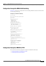
Configuration Example for MLP on LNS
Example 22-8 shows how to set up a tunnel on the GigabitEthernet interface on which the VPDN
member links are negotiated and added to the MLP bundle cloned from virtual template 500.