


20-25
Cisco 10000 Series Router Software Configuration Guide
OL-2226-23
Chapter 20 Configuring L2 Virtual Private Networks
Configuration Tasks for L2VPN
• On the egress side—The MPLS label is stripped, and up to two levels of VLAN tags are rewritten
per the configuration.
Only Unambiguous VLAN tagged Ethernet QinQ interfaces are supported in this release. The Ethernet
VLAN Q-in-Q rewrite of both VLAN Tags capability is supported only on Ethernet sub-interfaces with
a QinQ encapsulation and explicit pair of VLAN IDs defined.
Configuration Examples
Example 20-15 shows an unambiguous QinQ configured on GigE subinterface.
Example 20-15 Unambiguous QinQ
interface GigabitEthernet1/0/0.100
encapsulation dot1q 100 second-dot1q 200
xconnect 23.0.0.16 410 encapsulation mpls
Example 20-16 shows an ambiguous QinQ configured on a GigE subinterface.
Example 20-16 Ambiguous QinQ
interface GigabitEthernet1/0/0.200
encapsulation dot1q 200 second-dot1q 1000-2000,3000,3500-4000
xconnect 23.0.0.16 420 encapsulation mpls
interface GigabitEthernet1/0/0.201
encapsulation dot1q 201 second-dot1q any
xconnect 23.0.0.16 430 encapsulation mpls
Note Ambiguous inner VLAN IDs are not supported in this release.
Verifying QinQ AToM
Example 20-17 shows the command output of the show mpls l2transport vc command, which is used
to verify the VC set up in EoMPLS QinQ mode.
Example 20-17 show mpls l2transport vc Command Output
Local intf Local circuit Dest address VC ID Status
------------- -------------------------- --------------- ---------- ----------
Gi1/0/0.1 Eth VLAN:100/200 100.1.1.2 1 UP
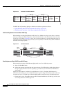
Remote Ethernet Port Shutdown
This Cisco IOS feature allows a service provider edge (PE) router on the local end of an Ethernet over
MPLS (EoMPLS) pseudowire to detect a remote link failure and shutdown of the Ethernet port on the
local customer edge (CE) router. Because the Ethernet port on the local CE router is shut down, the router
does not lose data by continuously sending traffic to the failed remote link. This is beneficial if the link
is configured as a static IP route.
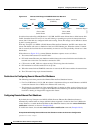
Figure 20-5 illustrates a condition in an EoMPLS wide area network (WAN) with a down Layer 2 tunnel
link between a CE1 router and the PE1 router. A CE2 router on the far side of the Layer 2 tunnel,
continues to forward traffic to CE1 through the L2 tunnel.