


20-33
Cisco 10000 Series Router Software Configuration Guide
OL-2226-23
Chapter 20 Configuring L2 Virtual Private Networks
Configuration Tasks for L2VPN
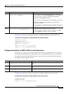
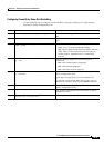
Configuring Frame Relay Same-Port Switching
Use the following steps to configure local Frame Relay same-port switching on a single interface,
beginning in global configuration mode.
Command Purpose
Step 1
Router(config)# frame-relay switching
Enables PVC switching on a Frame Relay DCE device or a
NNI.
Step 2
Router(config)# interface type number
Specifies the interface and enters interface configuration
mode.
Step 3
Router(config-if)# encapsulation frame-relay
[cisco | ietf]
Enables Frame Relay encapsulation.
• cisco—Cisco’s own encapsulation (default)
• ietf—Internet Engineering Task Force (IETF) standard
(RFC 1490). Use this keyword when connecting to
another vendor's equipment across a Frame Relay
network.
Step 4
Router(config-if)# frame-relay intf-type {dce |
dte | nni}
(Optional) Enables support for a particular type of
connection.
• dce—data communications equipment
• dte—data terminal equipment
• nni—network-to-network interface
Step 5
Router(config-if)# frame-relay interface-dlci
dlci switched
(Optional) Creates a switched PVC and enters Frame Relay
DLCI configuration mode.
Repeat Step 1 through Step 5 for each switched PVC.
If you do not create a Frame Relay PVC in this step, it is
automatically created in Step 8 by the connect command.
Step 6
Router(config-fr-dlci)# exit
Exits Frame Relay DLCI configuration mode and returns to
interface configuration mode.
Step 7
Router(config-if)# exit
Exits interface configuration mode and returns to global
configuration mode.
Step 8
Router(config)# connect connection-name
interface dlci interface dlci
Defines a connection between the two data links.