


1-9
Cisco 10000 Series Router Software Configuration Guide
OL-2226-23
Chapter 1 Broadband Aggregation and Leased-Line Overview
Broadband Architecture Models
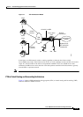
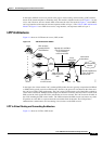
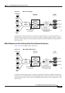
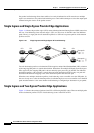
Figure 1-9 RBE to VRF Topology
In the figure, the wholesale provider uses physical or logical interfaces to separate the subscribers of
different retail providers. On the access side, the subscribers are uniquely placed in VRFs. A separate
physical or logical interface to each retail provider separates traffic for the different retail providers on
the network side.
RBE to Multiprotocol Label Switching Virtual Private Network Architecture
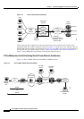
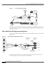
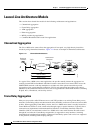
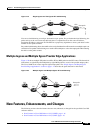
Figure 1-10 shows an RBE to MPLS VPN model.
Figure 1-10 RBE to MPLS VPN Topology
In the figure, the wholesale provider uses VPNs to separate the subscribers of different retail providers.
On the access side, the subscribers are uniquely placed in VRFs. A tag interface separates traffic for the
different retail providers on the network side. The MPLS VPN technology is used to assign tags in a VPN
aware manner.
CPE
RFC 2684 bridged
format PDUs
Provider 1
Provider 2
Provider n
ATM
access
network
VRF 1
VRF n
VRF 2
76268
Retail
providers
Wholesale
provider
Subscribers
L2
transport
network
Separate
logical/physical
interfaces. One per
retail provider
CPE
RFC 2684 bridged
format PDUs
Tag interface,
logically separated
into multiple VPNs
Provider 1
Provider 2
Provider n
ATM
access
network
VRF 1
VRF n
VRF 2
MPLS
network
76267
Retail
providers
Wholesale
provider
Subscribers