


20-30
Cisco 10000 Series Router Software Configuration Guide
OL-2226-23
Chapter 20 Configuring L2 Virtual Private Networks
Configuration Tasks for L2VPN
Enabling Other PE Devices to Transport Frame Relay Packets
You can configure an interface as a data terminal equipment (DTE) device or a data circuit-terminating
equipment (DCE) switch, or as a switch connected to a switch with network-to-network interface (NNI)
connections. Use the following command in interface configuration mode:
frame-relay intf-type [dce | dte | nni]
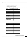
The following table explains the keywords:
Local Management Interface and Frame Relay over MPLS
Local Management Interface (LMI) is a protocol that communicates status information about permanent
virtual circuits (PVCs). When a PVC is added, deleted, or changed, the LMI notifies the endpoint of the
status change. LMI also provides a polling mechanism that verifies that a link is up.
LMI Process
To determine the PVC status, LMI checks that a PVC is available from the reporting device to the Frame
Relay end-user device. If a PVC is available, LMI reports that the status is “Active,” which means that
all interfaces, line protocols, and core segments are operational between the reporting device and the
Frame Relay end-user device. If any of those components is not available, the LMI reports a status of
“Inactive.”
Note Only the DCE and NNI interface types can report LMI status.
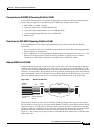
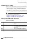
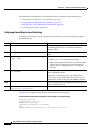
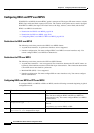
Figure 20-6 is a sample topology that illustrates how LMI works.
Figure 20-6 Sample LMI Topology
In Figure 20-6, note the following:
• CE1 and PE1 and PE2 and CE2 are Frame Relay LMI peers.
• CE1 and CE2 can be Frame Relay switches or end-user devices.
• Each Frame Relay PVC is composed of multiple segments.
• The DLCI value is local to each segment and is changed as traffic is switched from segment to
segment. Two Frame Relay PVC segments exist in
Figure 20-6; one is between PE1 and CE1 and
the other is between PE2 and CE2.
The LMI protocol behavior depends on DLCI-to-DLCI connections versus port-to-port connections.
Keyword Description
dce Enables the router or access server to function as a switch connected to a router.
dte Enables the router or access server to function as a DTE device. DTE is the default.
nni Enables the router or access server to function as a switch connected to a switch.
P PE2 CE2CE1 PE1
59525