


21-9
Cisco 10000 Series Router Software Configuration Guide
OL-2226-23
Chapter 21 Configuring L2VPN Interworking
Ethernet/VLAN to ATM AAL5 Interworking
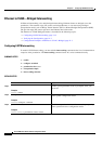
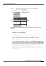
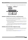
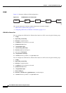
Figure 21-3 Protocol Stack for ATM AAL5 to Ethernet Local Switching Bridged Interworking
ATM AAL5 to VLAN 802.1Q Local Switching—Bridged Interworking
This interworking type provides interoperability between ATM attachment VC and Ethernet VLAN
attachment VC connected to the same PE router. As in the ATM to Ethernet case, Bridged encapsulation
is used, corresponding to Bridged (Ethernet) Interworking mechanism.
In case of Ethernet VLAN attachment, the VLAN ID is a service delimiter, so the VLAN header is not
included in the frame to and from the ATM CE.
• In the VLAN to ATM direction, the PE router discards the VLAN header from the Layer 2 packet.
The PE
router sends the frame to the ATM egress interface after encapsulating the L2 packet over
AAL5 using Bridged encapsulation.
• In the ATM to VLAN direction, the ATM header and bridged encapsulation are discarded and the
L2
packet is sent out with a VLAN header inserted following the destination/source MAC addresses.
The protocol stack for ATM to VLAN local switching is shown in Figure 21-3. The ATM side has an
encapsulation type of aal5snap.
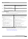
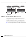
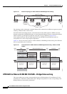
ATM AAL5 to Ethernet Port AToM—Bridged Interworking
This interworking type provides interoperability between ATM attachment VC and Ethernet attachment
VC connected to different PE routers. Bridged encapsulation is used, corresponding to the Bridged
(Ethernet) Interworking mechanism.
The interworking function is performed at the PE connected to the ATM attachment VC based on
Multiprotocol Encapsulation over ATM Adaptation Layer 5 (
Figure 21-4).
270310
ATM
CE
Eth
CE
ATM Ethernet
PE
ATM Header
MAC Header
DA
SA
MAC Header
DA
SA
Type/Length Type/Length
Remainder of
MAC Frame
Remainder of
MAC Frame
CPCS - UU CPI
Length
CRC
LAN FCS
LLC (AA-AA)
LLC(03) OUI (00)
OUI (80-C2)
PID (00-07)
PAD (00-00)