


1-6
Cisco 10000 Series Router Software Configuration Guide
OL-2226-23
Chapter 1 Broadband Aggregation and Leased-Line Overview
Broadband Architecture Models
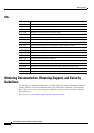
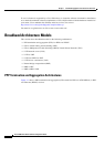
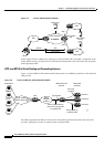
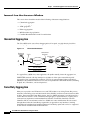
Figure 1-5 L2TP to VRF Architectural Model
In this model, the Cisco 10000 series router acts as the LNS with VRF 1 and VRF 2 configured on the
router. PPPoX
sessions are placed in an L2TP tunnel and terminated at the LNS where they are placed
in the appropriate VRF.
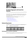
L2TP over MPLS to Virtual Routing and Forwarding Instance
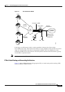
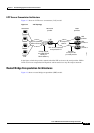
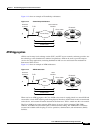
Figure 1-6 shows PPP in L2TP tunneled traffic transported over an MPLS tag interface to the wholesale
LNS provider.
Figure 1-6 L2TP over MPLS to VRF Architectural Model
The LNS encapsulates the PPP in L2TP sessions in IP packets and forwards them to the retail LNS
providers, placing the sessions for each provider in separate VRFs.
NSP
DSL
IP network
LNS
(home gateway)
NSP
NSPNSP
Cisco 10000
LNS
VRF 1
VRF 2
AAA server
AAA, DHCP
servers
PPP
L2TP tunnel
PPPoX
Client
69997
CPE
PPP in L2TP sessions.
Note L2TP tunnel traffic
is in global VRF
Retail LNS
providers
Provider 1
76272
Wholesale LNS
provider
LAC
Access network
(ATM or Ethernet)
MPLS
transport
network
Subscribers
Provider n
Provider 2
Each provider in
a different VRF.
Not a tag
interface
Tag interface