


1-4
Cisco 10000 Series Router Software Configuration Guide
OL-2226-23
Chapter 1 Broadband Aggregation and Leased-Line Overview
Broadband Architecture Models
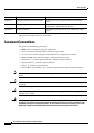
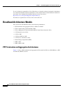
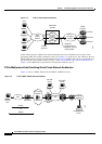
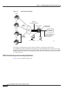
Figure 1-2 PTA to VRF Architectural Model
In this model, the Cisco 10000 series router terminates the sessions and places the sessions in the
appropriate VRF. This model is identical to the one in
Figure 1-3 on the access side. However, the two
models differ on the network side. The model in Figure 1-2 uses VRFs, does not use a tag interface on
the network side, and separates traffic at Layer 2. The “PTA to MPLS VPN Architectural Model” in
Figure 1-3 uses MPLS and a tag interface, and separates traffic at Layer 3.
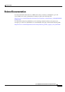
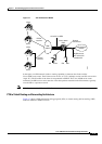
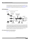
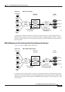
PTA to Multiprotocol Label Switching Virtual Private Network Architecture
Figure 1-3 shows a MPLS VPN model for PPPoA or PPPoE sessions.
Figure 1-3 PTA to MPLS VPN Architectural Model
CPE
Cisco 10000 ESR
Wholesale
provider
PPPoX
sessions
Retail
provider
Provider 1
Provider 2
Provider n
ATM
access
network
VRF 1
VRF n
VRF 2
69866
L2
transport
network
Separate
logical/physical
interface, one per
retail provider
SP MPLS
core
SP access
network
69868
Cisco 10000
ESR
LAN
Remote
user
DSLAM
DSL router
PE
CE
Customer
network
Customer AAA
server
SP AAA
server
SP DHCP
server
PPPoA
or
PPPoE
PE