


21-25
Cisco 10000 Series Router Software Configuration Guide
OL-2226-23
Chapter 21 Configuring L2VPN Interworking
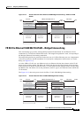
Ethernet/VLAN to Frame Relay Interworking
8. frame-relay switching
9. interface serial slot/subslot/port[:channel | .channel]
10. encapsulation frame-relay
11. frame-relay interface-dlci DLCI switched
12. connect mpls serial slot/subslot/port[:channel | .channel] DLCI l2transport
13. xconnect remote-ip-address vc-id pw-class name
You can configure the FR DLCI to Ethernet port feature on a PE2 router using the following steps:
1. config t
2. mpls label protocol ldp
3. interface Loopback<name>
4. ip address local-ip-address local-mask
5. pseudowire-class name
6. encapsulation mpls
7. interworking ip
8. interface [ fastethernet | gigabitethernet ] slot/subslot/port
9. xconnect remote-ip-address vc-id pw-class name
Note When configuring bridged interworking, the PE2 configuration does not include the
interworking ethernet command because it is treated as like-to-like, and also because the
attachment circuit is already an Ethernet port. However, when configuring routed interworking,
the PE2 configuration does include the interworking ip command.
The following example shows how to configure the FR DLCI to Ethernet port feature on a PE1 router,
using routed interworking:
config t
mpls label protocol ldp
interface Loopback100
ip address 10.0.0.100 255.255.255.255
pseudowire-class fr-eth
encapsulation mpls
interworking ip
frame-relay switching
interface serial 2/0/0:1
encapsulation frame-relay
frame-relay intf-type dce
frame-relay interface-dlci 567 switched
connect mpls serial 2/0/0:1 567 l2transport
xconnect 10.0.0.200 150 pw-class fr-eth
The following example shows how to configure the FR DLCI to an Ethernet port feature on a PE2 router,
using routed interworking:
config t
mpls label protocol ldp
interface Loopback200
ip address 10.0.0.200 255.255.255.255
pseudowire-class fr-eth
encapsulation mpls
interworking ip
interface gigabitethernet 5/1/0