


Introduction
Compaq ProLiant BL p-Class GbE Interconnect Switch User Guide 1-5
COMPAQ CONFIDENTIAL Codename: Vanilla Part Number: 263680-001 Last Saved On: 4/23/02 9:55 AM
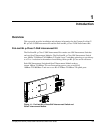
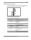
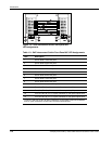
GbE Interconnect Switches
Two GbE Interconnect Switches in the ProLiant BL p-Class server blade enclosure provide
switch redundancy and redundant paths to the network ports on the server blades.
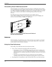
Each GbE Interconnect Switch has two Gigabit and two 10/100 Ethernet uplink ports and
direct connections to two of the four network controllers on each server blade. The four
network controllers one each server blade are NIC1, NIC2, NIC3, and Integrated Lights-Out
(iLO). NIC1 is Preboot eXecution Environment (PXE)-enabled. Each pair of GbE
Interconnect Switches consolidates up to thirty-two 10/100 Ethernet controllers on eight
servers into one-to-four Gigabit ports and one-to-four 10/100 uplink port on the back of the
system. This design eliminates up to 31 network cables from the back of the server blade
enclosure.
NOTE: Refer to the Compaq ProLiant BL p-Class System Setup and Installation Guide for
more information about Integrated Lights-Out (iLO) management and the Preboot eXecution
Environment (PXE).
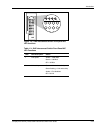
Redundant Crosslinks
The two GbE Interconnect Switches are connected through redundant 100-Mb/s crosslinks.
These two crosslinks provide an aggregate throughput of 200 Mb/s for traffic between the
GbE Interconnect Switches.
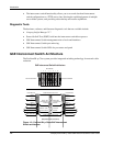
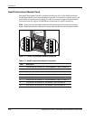
Redundant Paths to Servers
The three 10/100 NIC ports and the one iLO controller on each server are routed through the
enclosure backplane to different GbE Interconnect Switches. PXE NIC1 and NIC2 on each
server blade are routed to Switch A. NIC 3 and iLO on each server blade are routed to
Switch B. This configuration provides redundant paths to each server.
NOTE: On a heavily used system, using a single uplink port for all 24 NICs and 8 iLOs can cause a
traffic bottleneck. For example, if uplink 1 on Switch A is the only uplink used, all traffic to and from
NIC 3 and the iLO on any of the server blades must travel over the crosslinks between Switch A and
Switch B. The crossover links are intended as a failover route on the switch management link and
should not be used as a primary path. For optimum performance, use the uplink ports from both GbE
Interconnect Switches.
Supported Technologies
The ProLiant BL p-Class GbE Interconnect Switch supports the following technologies.
Refer to Chapter 3 and Chapter 4 for more details on these features.