Setting Up and Installing the GbE Interconnect Switch
Compaq ProLiant BL p-Class GbE Interconnect Switch User Guide 2-7
COMPAQ CONFIDENTIAL Codename: Vanilla Part Number: 263680-001 Last Saved On: 4/23/02 9:57 AM
GbE Interconnect Switch IP addresses are acquired by default using DHCP, therefore, each
GbE Interconnect Switch has a unique IP address. Each GbE Interconnect Switch can then
be remotely accessed from a central deployment workstation and an individual interconnect
switch configuration can be entered to meet specific network requirements. Refer to the
“Downloading Configuration File from TFTP Server” and “Saving Settings to a TFTP
Server”sections in Chapter 3 (console management interface) and “Saving Settings to
TFTP Server” and “Downloading a Configuration File on a TFTP Server” in Chapter 4
(Web-based management interface).
Cabling the GbE Interconnect Switch
After installing the GbE Interconnect Switch hardware and planning the configuration, cable
the GbE Interconnect Switch to your network.
IMPORTANT: If you are replacing an existing GbE Interconnect Switch or upgrading from an RJ-45
Patch Panel, and have strict security requirements:
• Do not cable the GbE Interconnect Switch until after configuration.
Or
• Connect the GbE Interconnect Switch to the optional Diagnostic Station. The Diagnostic Station
enables you to power up, configure, and diagnose a ProLiant p-Class server blade or a ProLiant
p-Class GbE Interconnect Switch outside of the rack environment.
To connect the interconnect modules to the network:
1. Connect your network cables to the interconnect modules. For connector locations, refer
to the section “QuadT Interconnect Module Panel” or “DualTSX Interconnect Module
Panel” in Chapter 1.
2. Gather your network cables for the right side of the rack.
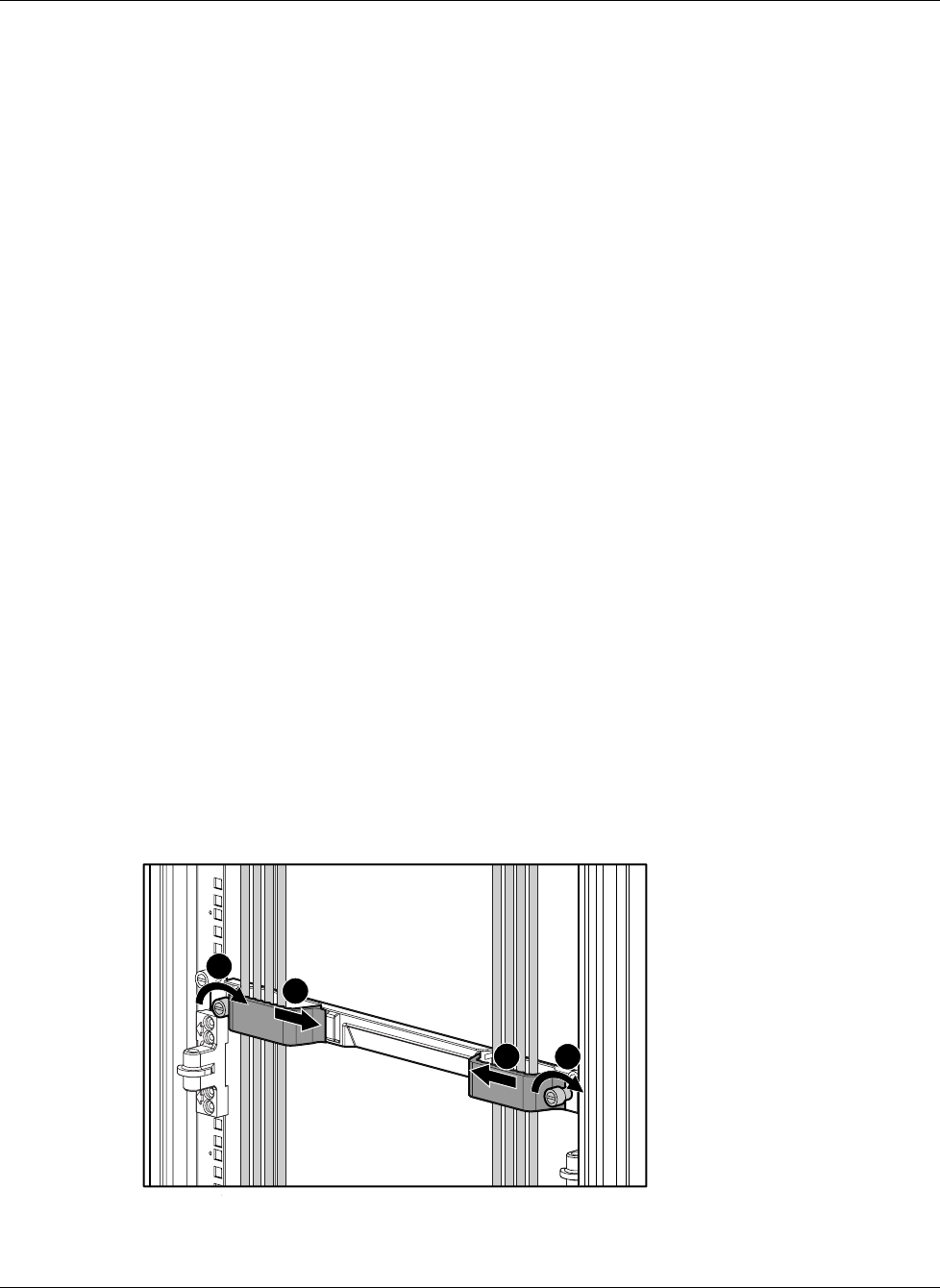
3. Insert the end of the cable retaining bracket (provided with the bus bar and power bus
boxes) into the cable bracket (1).
4. Tighten the thumbscrew to secure the cable retaining bracket over the cables (2).
1
1
2
2
Figure 2-3: Installing the cable-retaining bracket


