


Setting Up and Installing the GbE Interconnect Switch
2-4 Compaq ProLiant BL p-Class GbE Interconnect Switch User Guide
COMPAQ CONFIDENTIAL Codename: Vanilla Part Number: 263680-001 Last Saved On: 4/23/02 9:57 AM
4. Slide the GbE Interconnect Switch out of the communication bay.
5. Slide the new GbE Interconnect Switch fully into the communication bay.
6. Close the ejector lever.
7. If you saved the configuration file to a TFTP server, download the configuration. Refer to
the “Downloading Configuration File from a TFTP Server” section in Chapter 3 (console
management interface) and “Downloading a Configuration File on a TFTP Server” in
Chapter 4 (Web-based management interface).
Upgrading from RJ-45 Patch Panels
CAUTION: Removing a GbE Interconnect Switch from a powered enclosure will result in the
loss of network communications between the server blade and the GbE Interconnect Switch.
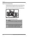
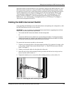
1. From the front side of the ProLiant BL p-Class server blade enclosure, unlock the ejector
lever and slide out the Patch Panels from the left and right communication bays.
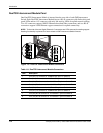
2. From the rear side of the server blade enclosure, slide out the top and bottom patch panel
RJ-45 modules (four total) from the left and right module bays and unplug the cables.
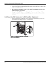
3. From the rear side of the server blade enclosure, insert the new interconnect modules
(two total) that came with the GbE Interconnect Switches into the top-left and top-right
module bays.
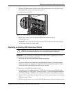
4. From the front side of the server blade enclosure, slide the GbE Interconnect Switch into
the left communication bay.
5. Lock the ejector lever.
6. Repeat steps 4 and 5 to install the second GbE Interconnect Switch in the right
communication bay.
Planning the GbE Interconnect Switch Configuration
Before you configure the GbE Interconnect Switch, Compaq recommends that you plan the
configuration. As you plan, consider your default settings, security issues and privileges, and
whether you want to configure each GbE Interconnect Switch manually or configure multiple
GbE Interconnect Switches at the same time.
Default Settings
The GbE Interconnect Switches ship with a default configuration in which all ports are
enabled and assigned a default virtual LAN (VLAN) with a VLAN ID (VID) equal to 1. This
default configuration simplifies your initial setup by allowing you to use a single uplink cable
(from any external Ethernet connector) to connect your server blade enclosure to your
network. You need to assess your particular server environment to determine any
requirements for other considerations.